FP410 specifications
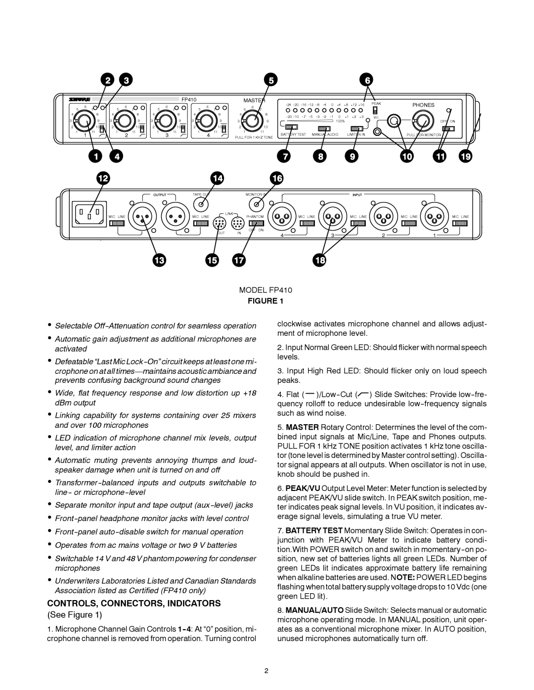
The Shure FP410 is a compact, portable dual-channel wireless receiver designed for professional audio applications, particularly in the fields of video production, broadcasting, and live events. It embodies Shure’s commitment to high-quality audio transmission, reliability, and ease of use, making it an ideal choice for audio professionals who demand superior performance in their equipment.One of the standout features of the FP410 is its dual-channel capability, allowing users to receive audio signals from two separate transmitters simultaneously. This is particularly beneficial in situations where multiple audio sources need to be captured independently, such as interviews or multi-person presentations. The unit operates in the 500 to 600 MHz frequency range, providing a wide selection of channels and minimizing the risk of interference from other wireless devices.
The FP410 is equipped with Shure's advanced digital signal processing technology, enabling it to deliver clear, high-fidelity audio with minimal latency. The unit utilizes a proprietary Automatic Frequency Selection feature, which scans the environment and selects the best available frequency, ensuring a stable and reliable connection. Additionally, it features a frequency diversity mode that provides even further protection against dropouts and interference by simultaneously receiving signals on two separate frequencies.
The design of the FP410 is rugged yet lightweight, making it suitable for both stationary setups and mobile use. It features a large, easy-to-read LCD screen that displays essential information, including battery life, signal strength, and channel selection, allowing users to monitor their setup at a glance. The receiver can be powered via AA batteries or an external power supply, adding flexibility for various field conditions.
Another notable characteristic of the FP410 is its versatility in connectivity options. It includes balanced XLR and unbalanced 1/4-inch output connections, providing compatibility with a range of audio devices, from cameras to mixers. This adaptability makes it a valuable tool for videographers, musicians, and sound engineers alike.
In summary, the Shure FP410 represents an advanced solution for wireless audio transmission. With its dual-channel operation, intelligent frequency selection, robust design, and versatile connectivity, it meets the demands of professional audio applications while ensuring exceptional sound quality and reliability. Whether for location shoots, live broadcasts, or stage performances, the FP410 is engineered to excel in any environment, solidifying Shure’s reputation as a leader in audio technology.

