Siemens 125-1957 RM Stpt MIN, RM Stpt MAX, RM Stpt Dial, AUX Temp, Disch Temp, MA Temp

Models: 125-1957

1 48
Download 48 pages 111 b
Page 34
Image 34

APOGEE Heat Pump Controller—Multi Stage Owner's Manual

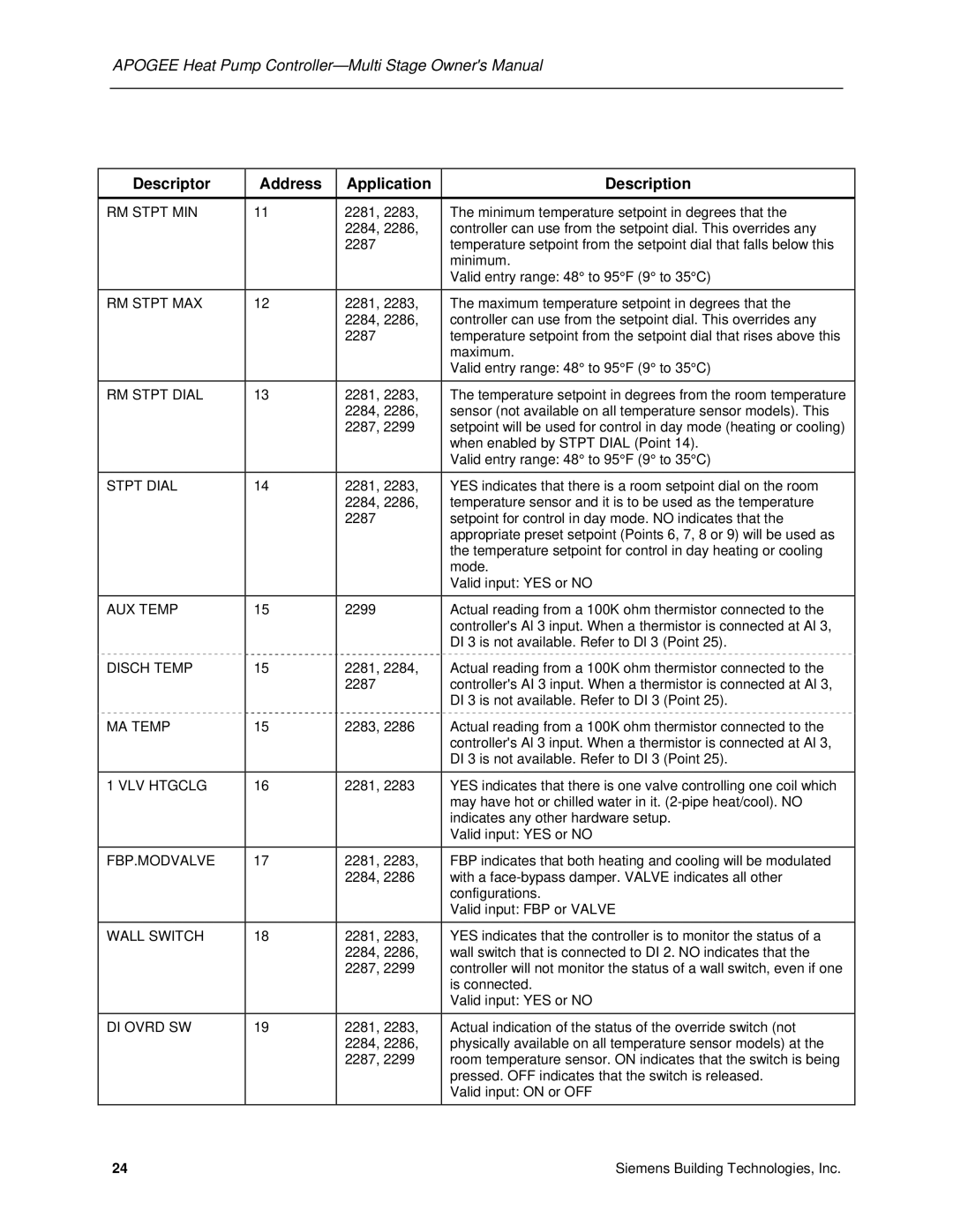
Descriptor

Address

Application

Description


RM STPT MIN

11

2281, 2283,

The minimum temperature setpoint in degrees that the


2284, 2286,

controller can use from the setpoint dial. This overrides any


2287

temperature setpoint from the setpoint dial that falls below this


minimum.


Valid entry range: 48° to 95°F (9° to 35°C)


RM STPT MAX

12

2281, 2283,

The maximum temperature setpoint in degrees that the


2284, 2286,

controller can use from the setpoint dial. This overrides any


2287

temperature setpoint from the setpoint dial that rises above this


maximum.


Valid entry range: 48° to 95°F (9° to 35°C)


RM STPT DIAL

13

2281, 2283,

The temperature setpoint in degrees from the room temperature


2284, 2286,

sensor (not available on all temperature sensor models). This


2287, 2299

setpoint will be used for control in day mode (heating or cooling)


when enabled by STPT DIAL (Point 14).


Valid entry range: 48° to 95°F (9° to 35°C)

STPT DIAL

14

2281, 2283,

YES indicates that there is a room setpoint dial on the room


2284, 2286,

temperature sensor and it is to be used as the temperature


2287

setpoint for control in day mode. NO indicates that the


appropriate preset setpoint (Points 6, 7, 8 or 9) will be used as


the temperature setpoint for control in day heating or cooling


mode.


Valid input: YES or NO

AUX TEMP

15

2299

Actual reading from a 100K ohm thermistor connected to the


controller's Al 3 input. When a thermistor is connected at Al 3,


DI 3 is not available. Refer to Dl 3 (Point 25).

DISCH TEMP

15

2281, 2284,

Actual reading from a 100K ohm thermistor connected to the


2287

controller's AI 3 input. When a thermistor is connected at Al 3,


DI 3 is not available. Refer to DI 3 (Point 25).

MA TEMP

15

2283, 2286

Actual reading from a 100K ohm thermistor connected to the


controller's Al 3 input. When a thermistor is connected at Al 3,


DI 3 is not available. Refer to DI 3 (Point 25).


1 VLV HTGCLG

16

2281, 2283

YES indicates that there is one valve controlling one coil which


may have hot or chilled water in it. (2-pipe heat/cool). NO


indicates any other hardware setup.


Valid input: YES or NO


FBP.MODVALVE

17

2281, 2283,

FBP indicates that both heating and cooling will be modulated


2284, 2286

with a face-bypass damper. VALVE indicates all other


configurations.


Valid input: FBP or VALVE


WALL SWITCH

18

2281, 2283,

YES indicates that the controller is to monitor the status of a


2284, 2286,

wall switch that is connected to DI 2. NO indicates that the


2287, 2299

controller will not monitor the status of a wall switch, even if one


is connected.


Valid input: YES or NO

DI OVRD SW

19

2281, 2283,

Actual indication of the status of the override switch (not


2284, 2286,

physically available on all temperature sensor models) at the


2287, 2299

room temperature sensor. ON indicates that the switch is being


pressed. OFF indicates that the switch is released.


Valid input: ON or OFF

24

Siemens Building Technologies, Inc.

Page 34
Image 34
Siemens 125-1957 RM Stpt MIN, RM Stpt MAX, RM Stpt Dial, AUX Temp, Disch Temp, MA Temp, VLV Htgclg, Fbp.Modvalve

125-1957 specifications

Siemens 125-1957, a notable creation of the German engineering giant Siemens, is recognized for its innovative design and advanced technology in the realm of electrical engineering. This model is emblematic of the mid-20th century's commitment to optimizing electrical machinery for industrial applications, contributing to enhanced productivity and efficiency.

One of the main features of the Siemens 125-1957 is its robust construction, designed to withstand the demanding environments of industrial settings. The body of the machine is built from high-grade materials, ensuring durability and longevity. It is also designed to minimize vibration and noise during operation, thus enhancing the user experience.

Technologically, the Siemens 125-1957 incorporates advanced electric motor technology, which provides reliable performance across a variety of applications. The motor is designed for high efficiency, allowing it to operate effectively under load while consuming less energy. This efficiency is crucial in industrial applications where operational costs are significant. The motor is also equipped with thermally protected windings, which prevent overheating and extend the service life of the equipment.

The 125-1957 model is characterized by its adaptability in various operational settings. It is compatible with a range of automation systems, making it a versatile choice for factories and production lines. Its design allows for easy integration with existing equipment, minimizing downtime during installation.

Moreover, the Siemens 125-1957 boasts a user-friendly interface, making it accessible for operators with varying levels of expertise. It comes with comprehensive safety features, including circuit protection and emergency stops, ensuring that it meets the strict industrial safety standards.

In summary, the Siemens 125-1957 represents a blend of robust design, advanced motor technology, and user-oriented features. With its energy-efficient performance and adaptability, it stands out as a key asset in industrial electrical engineering, demonstrating Siemens' commitment to innovation and quality in the manufacturing sector. This model continues to be relevant, supporting various industries in their pursuit of efficiency and reliability.