Programmer’s Guide
The scaler’s rear panel
|
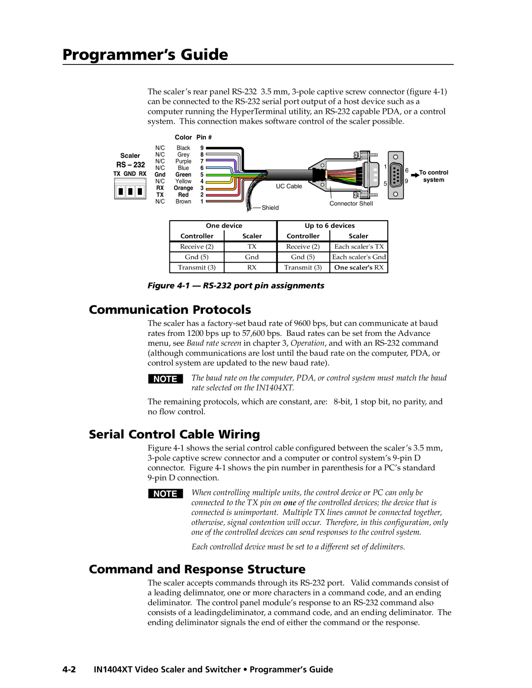
| Color | Pin # |
|
|
|
|
| N/C | Black | 9 |
|
|
|
|
Scaler | N/C | Grey | 8 |
|
|
|
|
| N/C | Purple | 7 |
| 1 |
|
|
| N/C | Blue | 6 |
| 6 | To control | |
| Gnd | Green | 5 |
|
| ||
|
|
|
| ||||
|
|
| 9 | system | |||
| N/C | Yellow | 4 | UC Cable | 5 | ||
| RX | Orange | 3 |
|
| ||
|
|
|
| ||||
| TX | Red | 2 |
|
|
|
|
| N/C | Brown | 1 | Shield | Connector Shell |
|
|
|
|
|
|
|
| ||
|
|
|
|
|
|
|
One device |
| Up to 6 devices | ||
Controller |
| Scaler | Controller | Scaler |
Receive (2) |
| TX | Receive (2) | Each scaler's TX |
|
|
|
|
|
Gnd (5) |
| Gnd | Gnd (5) | Each scaler's Gnd |
|
|
|
|
|
Transmit (3) |
| RX | Transmit (3) | One scaler's RX |
Figure 4-1 — RS-232 port pin assignments
Communication Protocols
The scaler has a
The baud rate on the computer, PDA, or control system must match the baud rate selected on the IN1404XT.
The remaining protocols, which are constant, are:
Serial Control Cable Wiring
Figure 4-1 shows the serial control cable configured between the scaler’s 3.5 mm, 3-pole captive screw connector and a computer or control system’s 9-pin D connector. Figure 4-1 shows the pin number in parenthesis for a PC’s standard 9-pin D connection.
When controlling multiple units, the control device or PC can only be connected to the TX pin on one of the controlled devices; the device that is connected is unimportant. Multiple TX lines cannot be connected together, otherwise, signal contention will occur. Therefore, in this configuration, only one of the controlled devices can send responses to the control system.
Each controlled device must be set to a different set of delimiters.
Command and Response Structure
The scaler accepts commands through its