IN1404XT
Video Scaler and Switcher
Instrucciones de seguridad Español
Safety Instructions English
Consignes de Sécurité Français
Sicherheitsanleitungen Deutsch
Table of Contents
Table of Contents, cont’d
IN1404XT Video Scaler and Switcher Table of Contents Iii
Iv IN1404XT Video Scaler and Switcher Table of Contents
One
About the Scaler
IN1404XT Video Scaler and Switcher Introduction
Introductiontroduction, cont’d
About this Manual
TP cable advantages
TP transmission
Introduction, cont’d
Features
IN1404XT Video Scaler and Switcher Introduction
Introduction, cont’d
Two
Mounting the Scaler
Installationstallation, cont’d
Installation Overview
IN1404XT Video Scaler and Switcher Installation
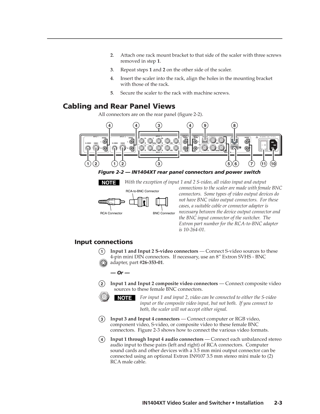
Input connections
Cabling and Rear Panel Views
Installation, cont’d
Standard output connections
TP video output connection
Termination of TP cable
Cable testing
Equalizing pair skew
Configuration
Power connection
RS-232 connection
Installation, cont’d
Three
Video controls
Front Panel Controls and Indicators
IN1404XT Video Scaler and Switcher Operation
Operationeration, cont’d
Menu control buttons
Audio controls
Menu operation
Power
Operation, cont’d
Front Panel Operations
Ma i n Me nu
Status indicators
Contrast screen
Menu system
Video menu
Brightness screen
Video menu flowchart
Sharpness screen
RGB Gain screen
Color Saturation screen
Hue screen
Comb/Trap selection screen
Reset Video screen
Gamma screen
Noise Filter screen
Balance screen
Reset Audio screen
10 IN1404XT Video Scaler and Switcher Operation
Treble screen
Gn a l Fo rma t
Input menu
Signal Format screen
12 IN1404XT Video Scaler and Switcher Operation
Aspect Ratio screen
10 Aspect ratio examples
Auto Switching screen
Horizontal Tracking screen
Phase screen
14 IN1404XT Video Scaler and Switcher Operation
Input Labels screen
Reset Input screen
Resolution screen
Output menu
Seamless Mode screen
16 IN1404XT Video Scaler and Switcher Operation
Refresh Rate screen
Size screen
Position screen
Sync Format screen
Blue Screen screen
Reset Output screen
Factory Reset screen
18 IN1404XT Video Scaler and Switcher Operation
Reset RS-232 screen
Baud Rate screen
Delimiters screen
20 IN1404XT Video Scaler and Switcher Operation
Enabling seamless switching
Setting up seamless switching
Seamless switching operation
Power-up shortcuts
Setting up a DVD source
Optimizing the Video
CRT displays selecting the optimum refresh rate
Resolution and refresh rates
CRT displays selecting the optimum resolution
22 IN1404XT Video Scaler and Switcher Operation
CRT Displays
Advanced Input submenu options
24 IN1404XT Video Scaler and Switcher Operation
Input blanking adjustment
14 Advanced input settings
26 IN1404XT Video Scaler and Switcher Operation
Active area adjustment
16 Incorrect active area setting
Total pixels adjustment
28 IN1404XT Video Scaler and Switcher Operation
Scan Type screen
Optimizing the Audio
Input Mode screen
Troubleshooting
30 IN1404XT Video Scaler and Switcher Operation
General checks
Problem Possible cause Solution No image appears
Specific problems
Does not appear
32 IN1404XT Video Scaler and Switcher Operation
Problem Possible cause Solution Image is cropped
Cannot be increased
34 IN1404XT Video Scaler and Switcher Operation
Edges
36 IN1404XT Video Scaler and Switcher Operation
Four
Communication Protocols
Serial Control Cable Wiring
Command and Response Structure
IN1404XT Video Scaler and Switcher Programmer’s Guide
Scaler Responses
Using the Command/Response Table
Programmer’s Guide, cont’d
Symbols
Input selection
Command Ascii Command Response Additional description
Autoswitch mode
Seamless switch mode
Output refresh rate
Output resolution
Input video type
Input video aspect ratio
Brightness
Contrast
RGB Gain
Color saturation
Hue
Sharpness
Horizontal tracking
Gamma
Noise filter
Comb/trap filter
10 IN1404XT Video Scaler and Switcher Programmer’s Guide
Bass
Memory preset
Volume
Freeze
Audio mute
12 IN1404XT Video Scaler and Switcher Programmer’s Guide
Disable front panel
Resets
Front panel buttons
Active area
Blanking
Scan type
14 IN1404XT Video Scaler and Switcher Programmer’s Guide
Input mode
Total pixels
Redetect the input mode
16 IN1404XT Video Scaler and Switcher Programmer’s Guide
AAppendix a
IN1404XT Video Scaler and Switcher Reference Information
Specifications
Audio
Included parts
Optional accessoriess
Reference Information, cont’d
Part Numbers
BNC-5 Mini HR Cable
Male-to-male VGA Cable
Pre-cut cables
BNC-4 Mini HR Cable Part number
BNC-4 Mini HR Cable Part number
Plenum BNC-5 Mini HR Cable Part number
Skew-free A/V cable Part number
Assorted cables and adapters Part number
Reference Information, cont’d
Extron’s Warranty
Extron Electronics, Japan
Extron Electronics, USA
Extron Electronics, Europe
Extron Electronics, Asia