n
ns
Installationstallation, cont’d
Installation Overview
To install and set up an IN1404XT video scaler and switcher for operation, perform the following steps:
1Disconnect power from all of the equipment, including the video and audio source(s), and the devices that will receive the output video and audio signals. Ensure the power switch on the scaler is off.
2Rack mount the scaler if desired. See Mounting the Scaler in this chapter.
3Connect the video and audio input cables. See Input connections in this chapter.
4Connect the standard video and audio output cables. See Standard output connections in this chapter.
5If desired, connect the TP cable between the scaler and an optional VTR001CM TP receiver and connect the output cables from the TP receiver to the display. See TP output connection in this chapter and refer to the VTT001CM and VTR001CM - Twisted Pair Transmitter and Receiver manual, part #
6If desired, connect the
7Connect the AC power cable. See Power connection in this chapter. Turn on the sources, video and audio destinations, and the scaler.
6Configure the scaler’s inputs and configure the output for the optimum image. See chapter 3, Operation and chapter 4, Programmer’s Guide.
Mounting the Scaler
The scaler includes four installed rubber feet. If you are going to rack mount the scaler, mount it before cabling it (see Rack mounting, below). The IN1404XT is exactly 1U high without the rubber feet; if you plan to rack mount the scaler with other equipment directly underneath it, the feet must be removed.
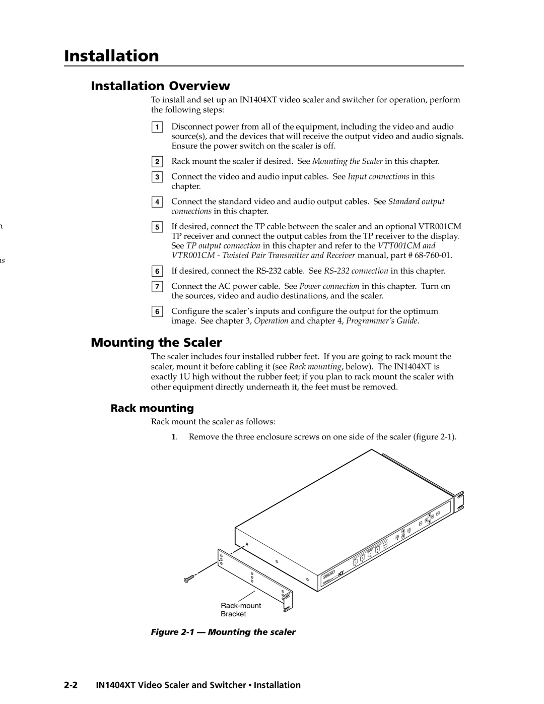
Rack mounting
Rack mount the scaler as follows:
1. Remove the three enclosure screws on one side of the scaler (figure
Bracket