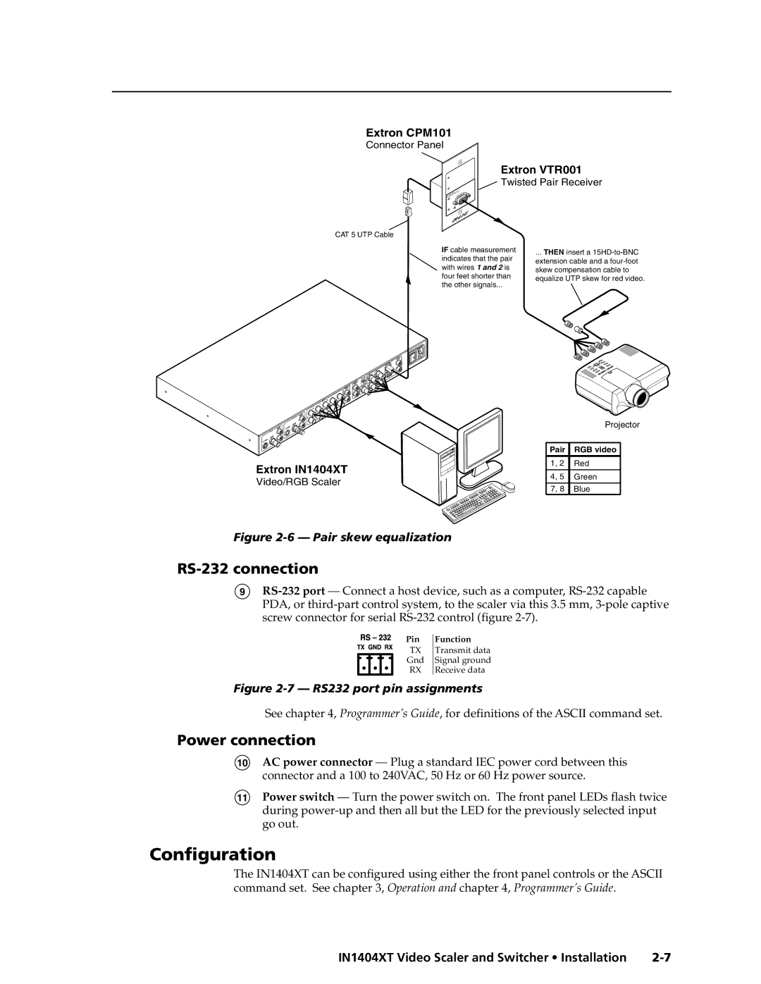
Extron CPM101
Connector Panel
Extron VTR001
| 0 | 0 | 1 | C M |
V T T | Pair | |||
Twisted |
| |||
Receiver VIDEO
![]() Twisted Pair Receiver
Twisted Pair Receiver
T
INPU
CAT 5 UTP Cable
IF cable measurement indicates that the pair with wires 1 and 2 is four feet shorter than the other signals...
... THEN insert a
Extron IN1404XT
Video/RGB Scaler
| Projector | |
|
|
|
Pair | RGB video |
|
1, 2 | Red |
|
|
|
|
4, 5 | Green |
|
|
|
|
7, 8 | Blue |
|
Figure 2-6 — Pair skew equalization
RS-232 connection
9
Pin
TX
Gnd
RX
Function
Transmit data Signal ground Receive data
Figure 2-7 — RS232 port pin assignments
See chapter 4, Programmer’s Guide, for definitions of the ASCII command set.
Power connection
10AC power connector — Plug a standard IEC power cord between this connector and a 100 to 240VAC, 50 Hz or 60 Hz power source.
11Power switch — Turn the power switch on. The front panel LEDs flash twice during
Configuration
The IN1404XT can be configured using either the front panel controls or the ASCII command set. See chapter 3, Operation and chapter 4, Programmer’s Guide.
IN1404XT Video Scaler and Switcher • Installation |