Appendix C. Frame Relay Examples
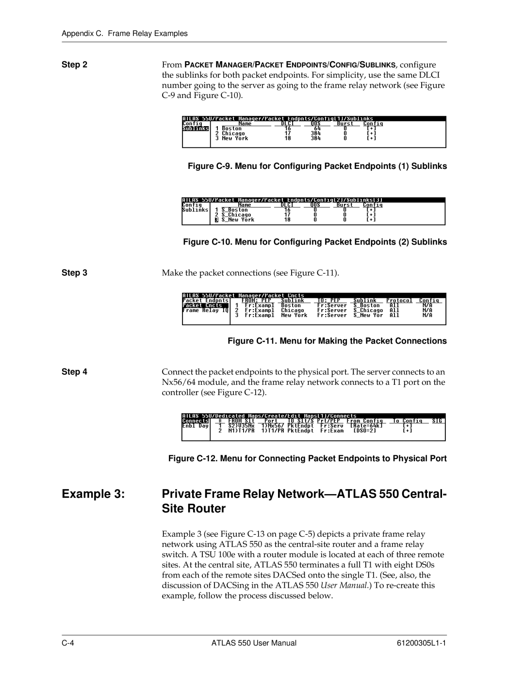
Step 2 | From PACKET MANAGER/PACKET ENDPOINTS/CONFIG/SUBLINKS, configure | |
| the sublinks for both packet endpoints. For simplicity, use the same DLCI | |
| number going to the server as going to the frame relay network (see Figure | |
|
| |
|
|
|
|
|
|
Figure C-9. Menu for Configuring Packet Endpoints (1) Sublinks
Figure C-10. Menu for Configuring Packet Endpoints (2) Sublinks
Step 3 | Make the packet connections (see Figure | |
|
|
|
|
|
|
|
| Figure | |
Step 4 | Connect the packet endpoints to the physical port. The server connects to an | ||
| Nx56/64 module, and the frame relay network connects to a T1 port on the | ||
| controller (see Figure | ||
|
|
|
|
|
|
|
|
Figure C-12. Menu for Connecting Packet Endpoints to Physical Port
Example 3: Private Frame Relay
Example 3 (see Figure
ATLAS 550 User Manual |