Chapter 2. Installation
Table
|
| Table |
|
|
|
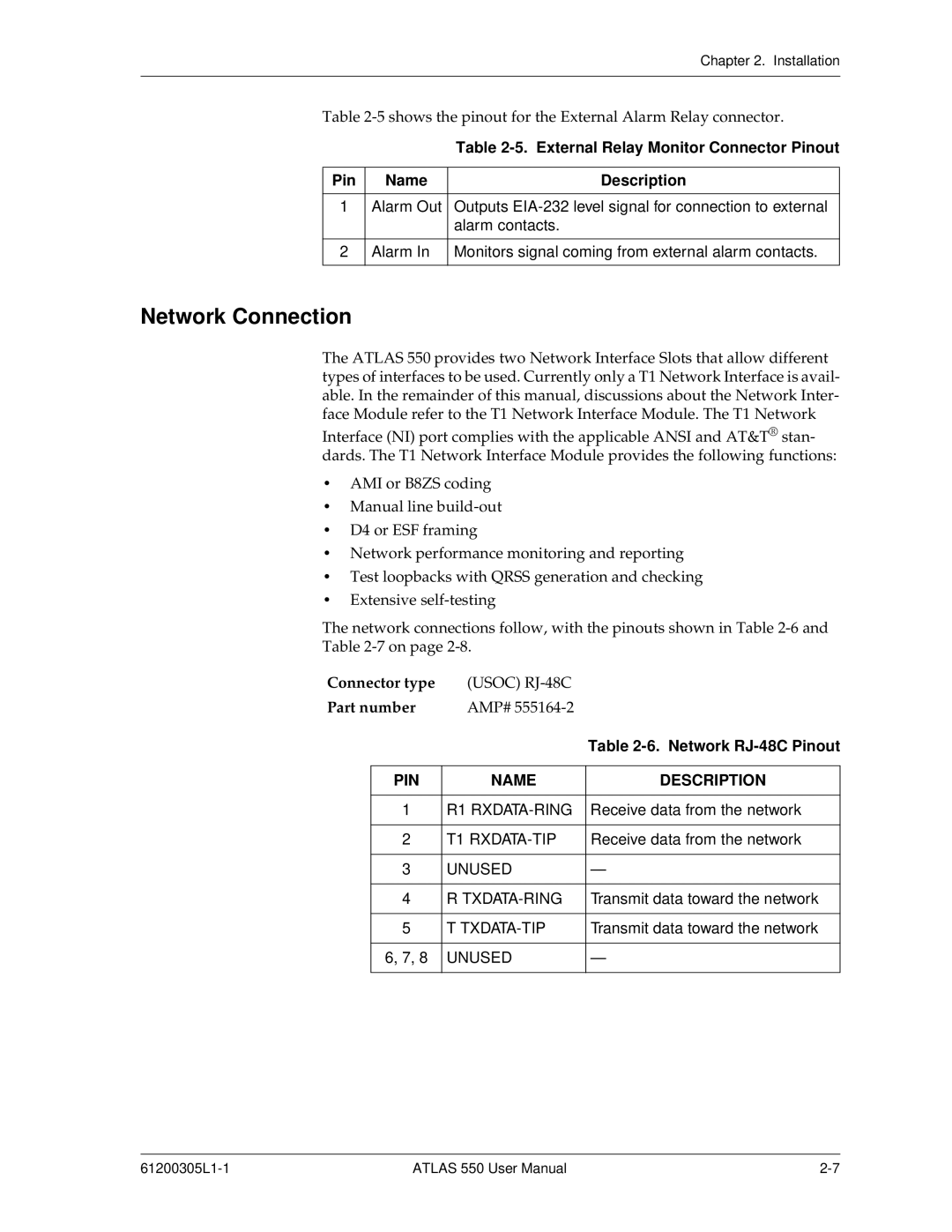
Pin | Name | Description |
|
|
|
1 | Alarm Out | Outputs |
|
| alarm contacts. |
|
|
|
2 | Alarm In | Monitors signal coming from external alarm contacts. |
|
|
|
Network Connection
The ATLAS 550 provides two Network Interface Slots that allow different types of interfaces to be used. Currently only a T1 Network Interface is avail- able. In the remainder of this manual, discussions about the Network Inter- face Module refer to the T1 Network Interface Module. The T1 Network
Interface (NI) port complies with the applicable ANSI and AT&T® stan- dards. The T1 Network Interface Module provides the following functions:
•AMI or B8ZS coding
•Manual line
•D4 or ESF framing
•Network performance monitoring and reporting
•Test loopbacks with QRSS generation and checking
•Extensive
The network connections follow, with the pinouts shown in Table
Table
Connector type | (USOC) |
| |
Part number | AMP# |
| |
|
|
| Table |
|
|
|
|
| PIN | NAME | DESCRIPTION |
|
|
|
|
| 1 | R1 | Receive data from the network |
|
|
|
|
| 2 | T1 | Receive data from the network |
|
|
|
|
| 3 | UNUSED | — |
|
|
|
|
| 4 | R | Transmit data toward the network |
|
|
|
|
| 5 | T | Transmit data toward the network |
|
|
|
|
| 6, 7, 8 | UNUSED | — |
|
|
|
|
ATLAS 550 User Manual |