Chapter 2. Installation
| Network 1 |
|
|
| Supplemental |
|
|
|
| ||||
|
| Blank Panel |
|
|
|
| |||||||
| Connection |
| Covering an | Earth |
|
| Power |
| |||||
| Port |
| Unused Option Slot | Ground Lug | Switch |
| |||||||
| 1 |
|
| 3 |
|
|
|
| O I |
|
|
|
|
|
|
|
|
|
|
|
| O | I |
|
|
| |
|
|
|
|
|
|
|
|
| CAUTION: | AC Power | |||
| 2 |
|
| 4 |
|
|
|
|
| WITHSAME | AGAINST | ||
COVERED WITH BLANK PANELS |
|
|
|
|
|
|
| TYPE AND | RISK OF FIRE, REPLACE ONLY | FOR CONTINUED PROTECTION | Receptacle | ||
|
|
|
|
|
|
|
|
| |||||
| NETWORK 1 |
| NETWORK 2 |
|
|
| FUSE RATING: 2A/250V |
| |||||
NETWORK | NETWORK | MON |
|
| ETHERNET | CONTROL | RELAY | ALARM |
| ||||
|
|
|
|
|
| ||||||||
BEALLEMPTYSLOTSMUST | IN OUT | IN OUT |
|
|
|
|
|
|
| Alarm Relay | |||
|
|
|
|
|
|
|
|
|
|
|
|
| |
| T1 NETWORK MODULE | TEST | 500 Series |
|
| IN | OUT | MON | NC NO COM GND | Connection | |||
|
|
|
| ||||||||||
| Network 1 | Bantam | Blank Panel | Control/ |
| External Alarm Relay | |||||||
| Test Jacks | Covering an | Ethernet | Chain |
|
| Monitor Connection | ||||||
| Connection |
|
| Unused Network Slot | 10/100BaseT | In |
| Control/ |
|
|
| ||
| Port |
|
|
| Connection |
|
|
|
|
|
| ||
|
|
|
|
|
|
| Chain |
|
|
| |||
|
|
|
|
| Port |
|
|
|
|
|
| ||
|
|
|
|
|
|
|
| Out |
|
|
| ||
|
|
|
|
|
|
|
|
|
|
|
| ||
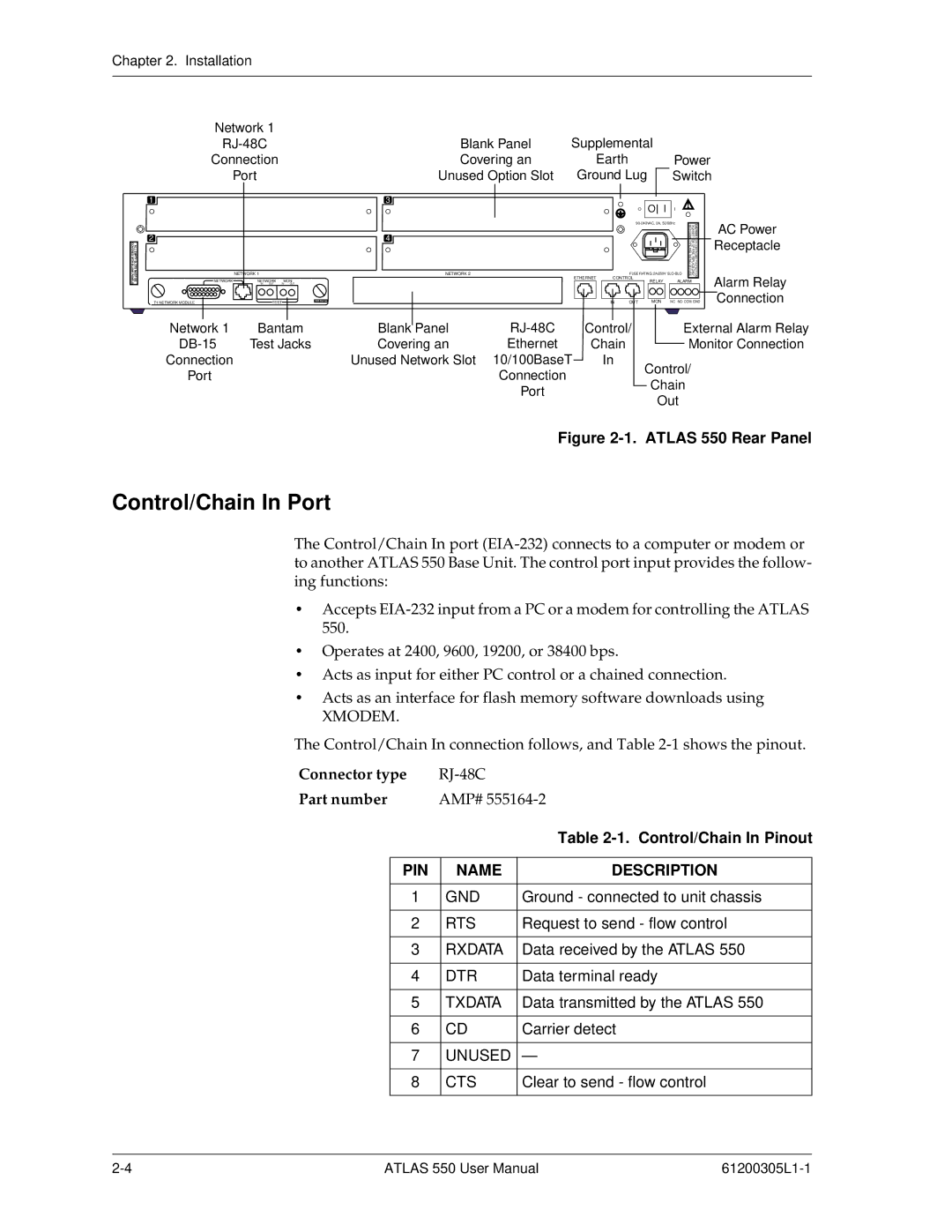
Figure 2-1. ATLAS 550 Rear Panel
Control/Chain In Port
The Control/Chain In port
•Accepts
•Operates at 2400, 9600, 19200, or 38400 bps.
•Acts as input for either PC control or a chained connection.
•Acts as an interface for flash memory software downloads using
XMODEM.
The Control/Chain In connection follows, and Table
Connector type |
| |||
Part number | AMP# | |||
|
|
|
| Table |
|
|
|
|
|
| PIN |
| NAME | DESCRIPTION |
|
|
|
|
|
| 1 |
| GND | Ground - connected to unit chassis |
|
|
|
|
|
| 2 |
| RTS | Request to send - flow control |
|
|
|
|
|
| 3 |
| RXDATA | Data received by the ATLAS 550 |
|
|
|
|
|
| 4 |
| DTR | Data terminal ready |
|
|
|
|
|
| 5 |
| TXDATA | Data transmitted by the ATLAS 550 |
|
|
|
|
|
| 6 |
| CD | Carrier detect |
|
|
|
|
|
| 7 |
| UNUSED | — |
|
|
|
|
|
| 8 |
| CTS | Clear to send - flow control |
|
|
|
|
|
ATLAS 550 User Manual |