Chapter 10. Dedicated Maps
Example 1 Setting Trunk Conditioning
The trunk conditioning process (see also, T1 Trunk Conditioning Service on page
Use the trunk conditioning menu items T1 FAULT SIGNALING (to set the state of the signaling bits) and T1 TROUBLE CODE VALUE (to set the state of the data bits) for this process. You can set trunk conditioning for each end of each T1-
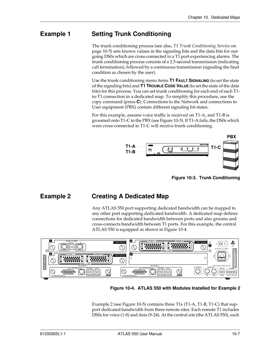
For this example, assume voice traffic is received on
T1-A
T1-B
PBX
|
|
|
|
|
|
| ATLAS 550 |
| 1 | 2 | 1 | 2 | 3 | 4 |
|
POWER | OK | OK | STATUS |
|
|
| |
SYSTEM | TEST | TEST | ONLINE |
|
|
| |
ETHERNET | ERROR | ERROR | TEST |
|
|
|
|
REMOTE | ALARM | ALARM |
|
| MODULES |
|
|
|
| NETWORK |
|
|
|
|
|
| CRAFT |
|
|
|
|
|
|
| ACO |
|
|
|
|
|
|
Figure 10-3. Trunk Conditioning
Example 2 Creating A Dedicated Map
Any ATLAS 550 port supporting dedicated bandwidth can be mapped to any other port supporting dedicated bandwidth. A dedicated map defines connections for dedicated bandwidth between ports and also grooms and
| 1 | 1 | DUAL T1/PRI | 2 |
|
|
|
| 500 Series | 3 | PORT 1 |
|
|
| PORT 2 | 500 Series |
| O | I |
|
|
|
| ||
|
|
| MON |
|
|
|
|
|
|
|
|
|
|
|
|
|
|
| O | I |
|
|
| ||
|
|
|
|
|
|
|
|
|
|
|
|
|
|
|
|
|
|
|
|
|
| ||||
|
|
|
|
|
|
|
|
|
|
|
|
|
|
|
|
|
|
| WITHSAME | AGAINST | CAUTION: | ||||
|
|
|
|
|
|
|
|
|
|
|
|
| DUAL V.35 |
|
|
|
|
|
|
| |||||
| 2 |
|
|
|
|
|
|
|
| 4 |
|
|
|
|
|
|
|
|
|
|
|
| |||
COVERED WITH BLANK PANELS |
| PORT 1 |
|
| PORT 2 |
| 500 Series |
|
|
|
|
|
|
|
|
|
|
|
| TYPE | RISK OF FIRE, REPLACE ONLY | FOR CONTINUED PROTECTION | |||
ALL EMPTY SLOTS MUST BE |
|
|
|
|
|
|
|
|
|
|
|
|
|
|
|
|
|
|
|
| |||||
|
| DUAL V.35 |
|
|
|
|
|
|
|
|
|
|
|
|
|
|
|
|
|
| AND RATING OF | ||||
|
|
|
|
|
|
|
|
|
|
|
|
|
|
|
|
|
|
|
| FUSE | |||||
|
| NETWORK 1 |
|
|
|
|
|
|
| NETWORK 2 |
|
|
|
|
|
| FUSE RATING: 2A/250V | ||||||||
| NETWORK | NETWORK | MON |
|
|
| NETWORK | NETWORK | MON |
| ETHERNET | CONTROL | RELAY |
| ALARM | ||||||||||
|
|
|
|
|
|
|
|
| |||||||||||||||||
|
| IN | OUT | IN | OUT |
|
|
|
| IN | OUT | IN | OUT |
|
|
|
|
|
|
|
| ||||
|
| T1 NETWORK MODULE |
|
| TEST |
| 500 Series | T1 NETWORK MODULE |
|
| TEST |
| 500 Series |
| IN | OUT | MON |
| NC NO COM GND | ||||||
|
|
|
|
|
|
|
|
|
|
|
| ||||||||||||||
Figure 10-4. ATLAS 550 with Modules Installed for Example 2
Example 2 (see Figure
ATLAS 550 User Manual |