Chapter 4 Using the Front Panel
OVERVIEW
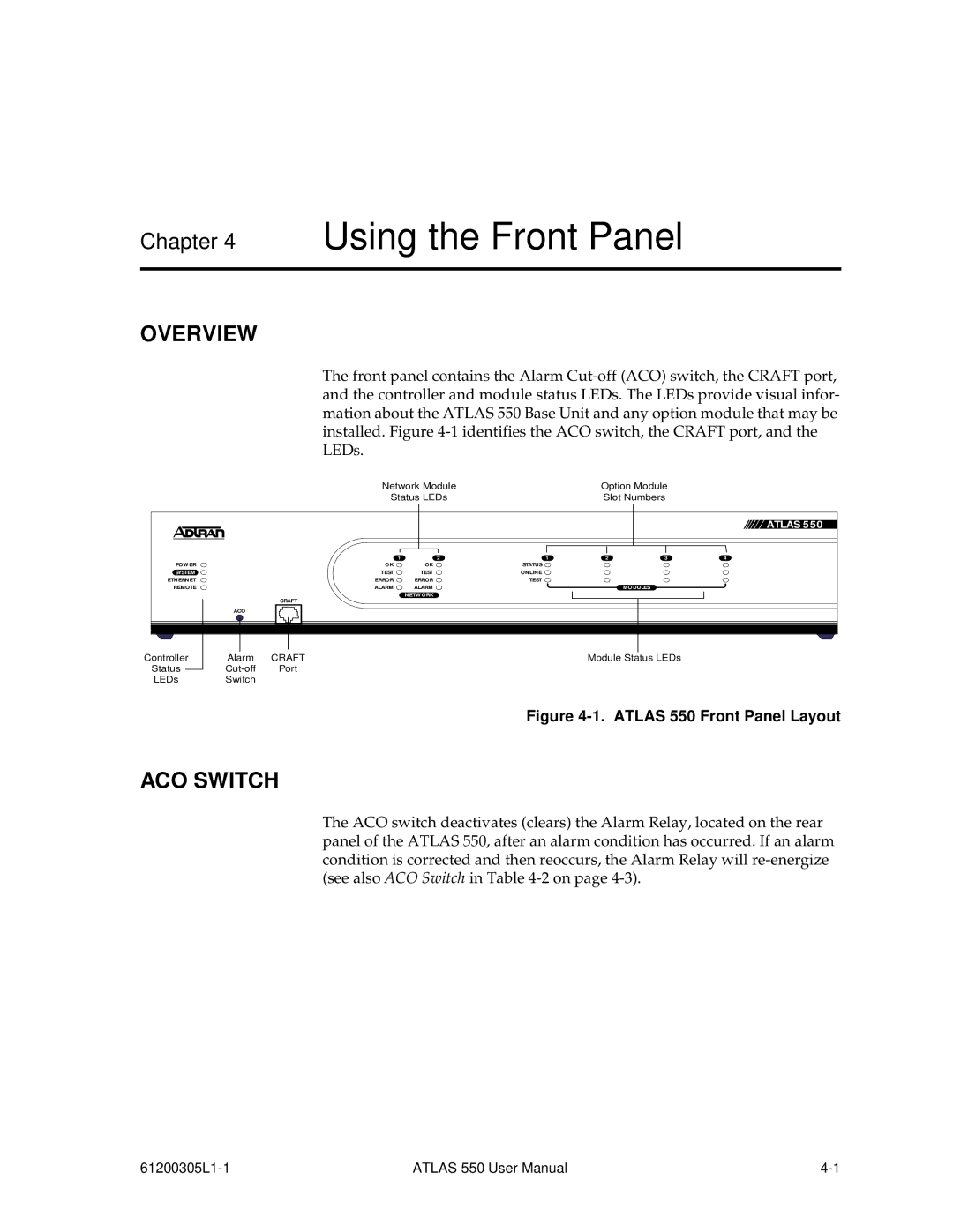
The front panel contains the Alarm
Network Module | Option Module |
Status LEDs | Slot Numbers |
|
|
|
|
|
|
| ATLAS 550 |
|
| 1 | 2 | 1 | 2 | 3 | 4 |
POWER |
| OK | OK | STATUS |
|
|
|
SYSTEM |
| TEST | TEST | ONLINE |
|
|
|
ETHERNET |
| ERROR | ERROR | TEST |
|
|
|
REMOTE |
| ALARM | ALARM |
|
| MODULES |
|
|
|
| NETWORK |
|
|
|
|
|
| CRAFT |
|
|
|
|
|
| ACO |
|
|
|
|
|
|
Controller | Alarm | CRAFT |
|
| Module Status LEDs |
| |
Status | Port |
|
|
|
|
| |
LEDs | Switch |
|
|
|
|
|
|
Figure 4-1. ATLAS 550 Front Panel Layout
ACO SWITCH
The ACO switch deactivates (clears) the Alarm Relay, located on the rear panel of the ATLAS 550, after an alarm condition has occurred. If an alarm condition is corrected and then reoccurs, the Alarm Relay will
ATLAS 550 User Manual |