Chapter 2. Installation
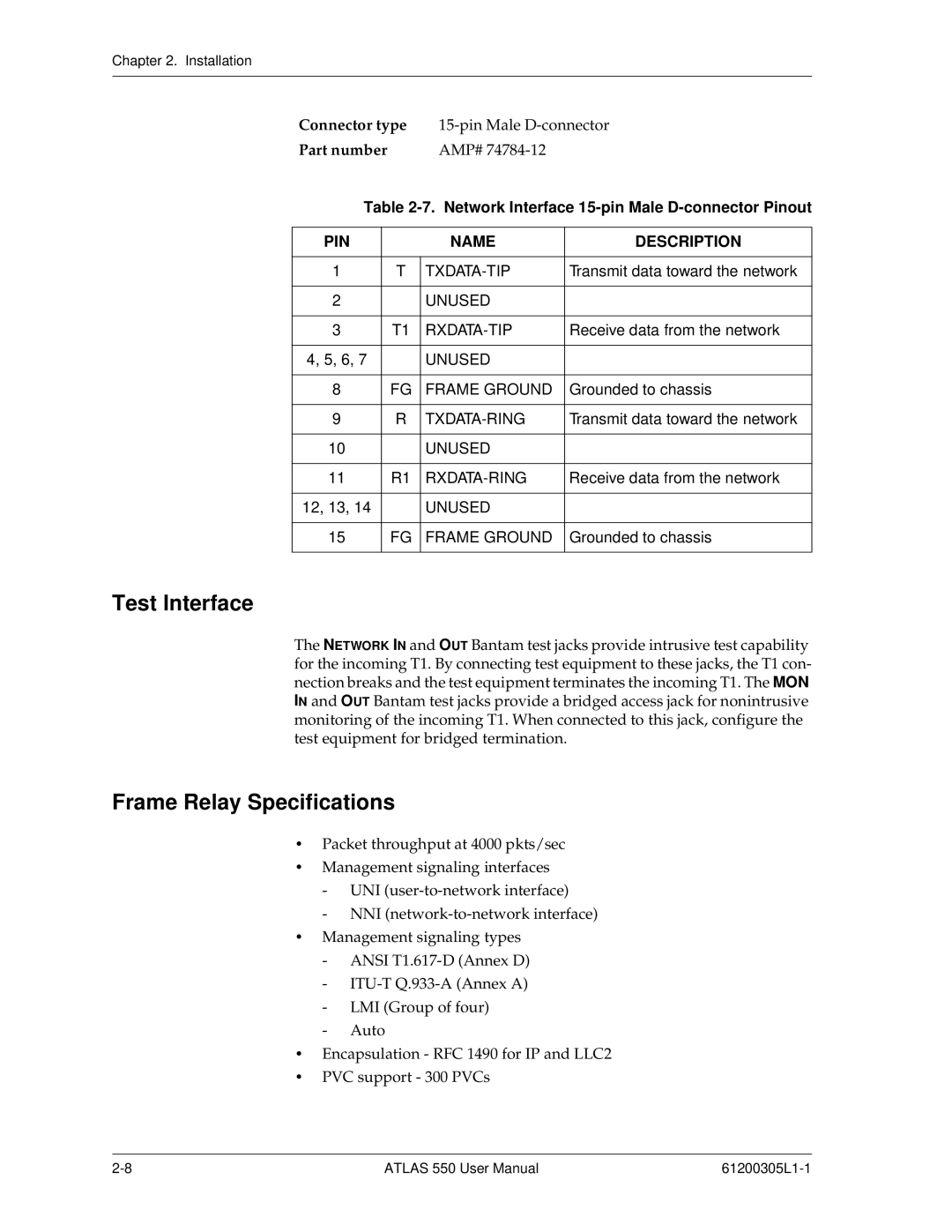
Connector type | ||||
Part number |
| AMP# |
| |
Table | ||||
|
|
|
| |
PIN |
|
| NAME | DESCRIPTION |
|
|
|
|
|
1 |
| T | Transmit data toward the network | |
|
|
|
|
|
2 |
|
| UNUSED |
|
|
|
|
|
|
3 |
| T1 | Receive data from the network | |
|
|
|
|
|
4, 5, 6, 7 |
|
| UNUSED |
|
|
|
|
|
|
8 |
| FG | FRAME GROUND | Grounded to chassis |
|
|
|
|
|
9 |
| R | Transmit data toward the network | |
|
|
|
|
|
10 |
|
| UNUSED |
|
|
|
|
|
|
11 |
| R1 | Receive data from the network | |
|
|
|
|
|
12, 13, 14 |
|
| UNUSED |
|
|
|
|
|
|
15 |
| FG | FRAME GROUND | Grounded to chassis |
|
|
|
|
|
Test Interface
The NETWORK IN and OUT Bantam test jacks provide intrusive test capability for the incoming T1. By connecting test equipment to these jacks, the T1 con- nection breaks and the test equipment terminates the incoming T1. The MON IN and OUT Bantam test jacks provide a bridged access jack for nonintrusive monitoring of the incoming T1. When connected to this jack, configure the test equipment for bridged termination.
Frame Relay Specifications
•Packet throughput at 4000 pkts/sec
•Management signaling interfaces
-UNI
-NNI
•Management signaling types
-ANSI
-
-LMI (Group of four)
-Auto
•Encapsulation - RFC 1490 for IP and LLC2
•PVC support - 300 PVCs
ATLAS 550 User Manual |