Appendix B. OSI Model and Frame Relay Technology Overview
gotiation of the bandwidth parameters during the circuit setup. SVCs are currently unavailable from most frame relay providers, and ATLAS only supports PVCs.
PVC Physical Connections
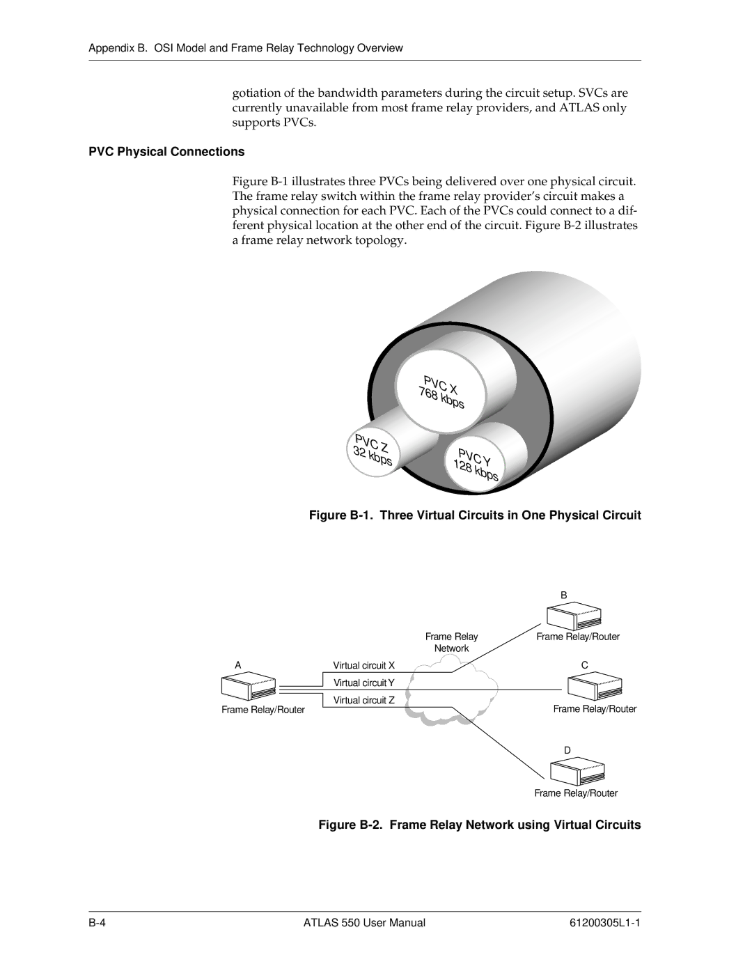
Figure B-1 illustrates three PVCs being delivered over one physical circuit. The frame relay switch within the frame relay provider’s circuit makes a physical connection for each PVC. Each of the PVCs could connect to a dif- ferent physical location at the other end of the circuit. Figure B-2 illustrates a frame relay network topology.
| PVC | X |
| |
| 768 |
|
| |
|
| kbps |
| |
PVC |
|
|
| |
32 | Z |
| PVCY | |
kbps |
| |||
|
| |||
|
|
| 128 | kbps |
|
|
|
| |
Figure B-1. Three Virtual Circuits in One Physical Circuit
|
| B |
| Frame Relay | Frame Relay/Router |
| Network |
|
A | Virtual circuit X | C |
| Virtual circuit Y |
|
Frame Relay/Router | Virtual circuit Z | Frame Relay/Router |
| ||
|
| D |
|
| Frame Relay/Router |
Figure B-2. Frame Relay Network using Virtual Circuits
ATLAS 550 User Manual |