| Chapter 4. Using the Front Panel |
|
|
| Table |
|
|
Feature | Description |
|
|
|
|
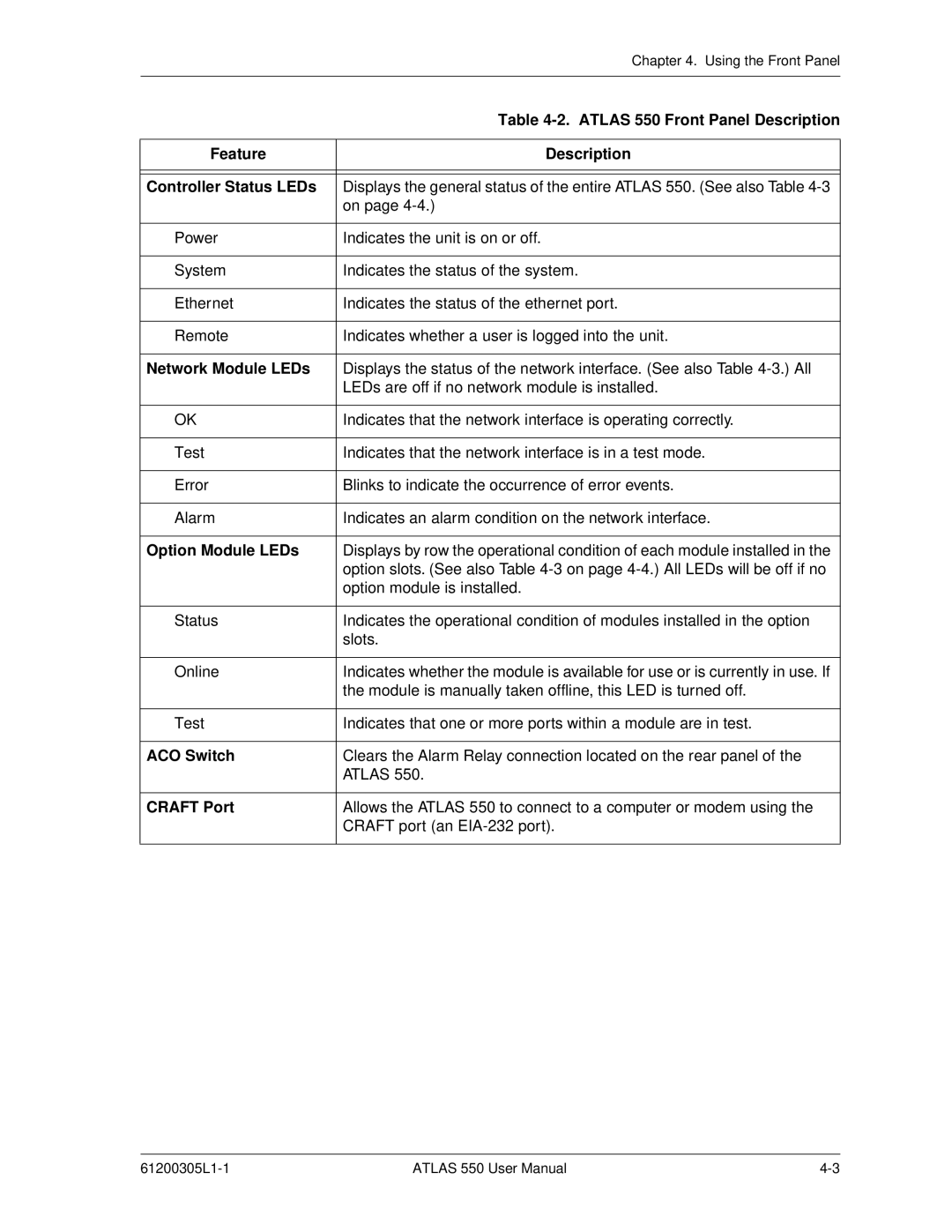
Controller Status LEDs | Displays the general status of the entire ATLAS 550. (See also Table |
| on page |
|
|
Power | Indicates the unit is on or off. |
|
|
System | Indicates the status of the system. |
|
|
Ethernet | Indicates the status of the ethernet port. |
|
|
Remote | Indicates whether a user is logged into the unit. |
|
|
Network Module LEDs | Displays the status of the network interface. (See also Table |
| LEDs are off if no network module is installed. |
|
|
OK | Indicates that the network interface is operating correctly. |
|
|
Test | Indicates that the network interface is in a test mode. |
|
|
Error | Blinks to indicate the occurrence of error events. |
|
|
Alarm | Indicates an alarm condition on the network interface. |
|
|
Option Module LEDs | Displays by row the operational condition of each module installed in the |
| option slots. (See also Table |
| option module is installed. |
|
|
Status | Indicates the operational condition of modules installed in the option |
| slots. |
|
|
Online | Indicates whether the module is available for use or is currently in use. If |
| the module is manually taken offline, this LED is turned off. |
|
|
Test | Indicates that one or more ports within a module are in test. |
|
|
ACO Switch | Clears the Alarm Relay connection located on the rear panel of the |
| ATLAS 550. |
|
|
CRAFT Port | Allows the ATLAS 550 to connect to a computer or modem using the |
| CRAFT port (an |
|
|
ATLAS 550 User Manual |