Appendix B. OSI Model and Frame Relay Technology Overview
Data Link Connection Identifier (DLCI)
An address called a Data Link Connection Identifier (DLCI) uniquely iden- tifies each of the virtual circuits in the frame relay network. A DLCI does not address the equipment at the far end of the virtual circuit, but addresses the next piece of frame relay equipment within the network. The next piece of frame relay equipment now becomes responsible for transporting all frames from the incoming port to the appropriate outgoing port.
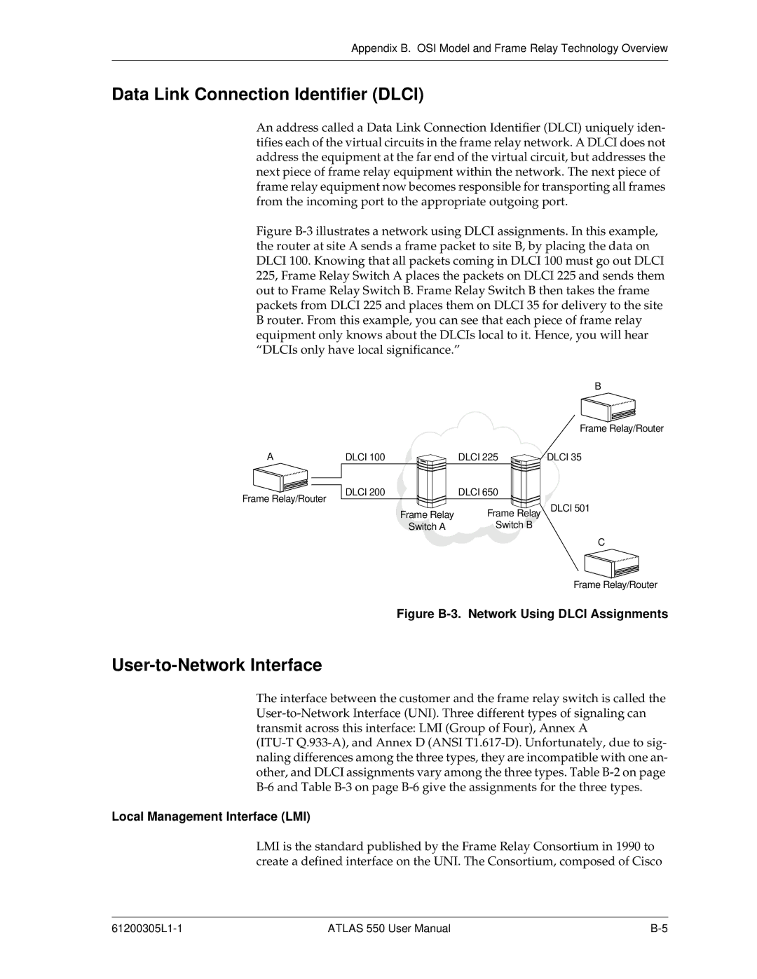
Figure B-3 illustrates a network using DLCI assignments. In this example, the router at site A sends a frame packet to site B, by placing the data on DLCI 100. Knowing that all packets coming in DLCI 100 must go out DLCI 225, Frame Relay Switch A places the packets on DLCI 225 and sends them out to Frame Relay Switch B. Frame Relay Switch B then takes the frame packets from DLCI 225 and places them on DLCI 35 for delivery to the site B router. From this example, you can see that each piece of frame relay equipment only knows about the DLCIs local to it. Hence, you will hear “DLCIs only have local significance.”
B
Frame Relay/Router
A | DLCI 100 | DLCI 225 | DLCI 35 |
Frame Relay/Router | DLCI 200 | DLCI 650 |
|
|
| DLCI 501 | |
| Frame Relay | Frame Relay | |
| Switch A | Switch B |
|
C
Frame Relay/Router
Figure B-3. Network Using DLCI Assignments
User-to-Network Interface
The interface between the customer and the frame relay switch is called the
Local Management Interface (LMI)
LMI is the standard published by the Frame Relay Consortium in 1990 to create a defined interface on the UNI. The Consortium, composed of Cisco
ATLAS 550 User Manual |