Chapter 10. Dedicated Maps
|
| Instructions for Defining the Data Connections | |
|
| (DS0s | |
|
|
| |
|
|
| |
Step | Action | ||
|
|
| |
1 |
| Name your map by navigating to DEDICATED MAPS / CREATE/EDIT | |
| MAPS and entering a name. | ||
|
| ||
|
|
| |
|
| Navigate to the CREATE/EDIT MAPS field, CONNECTS. | |
2 |
| This field defines the connections necessary to route the required | |
|
| bandwidth. | |
|
|
| |
3 |
| For | |
|
|
| |
4 |
| Select and define the “from”PORT as 1)T1/PRI. | |
|
|
| |
5 |
| Select and define TO SLT/S as S2) V35NX; S2) represents Slot 2. | |
|
|
| |
6 |
| Select and define PRT/PEP as 1) NX56/64; 1) represents Port 1 of | |
| Slot 2. | ||
|
| ||
|
|
| |
7 |
| Select and define FROM CONFIG DS0s as | |
|
|
| |
8 |
| Set the V.35 to operate at 64k per DS0 in TO CONFIG, [RATE=64K]. | |
|
|
| |
9 |
| Repeat these steps for the remaining data connections (i.e., | |
| and | ||
|
| ||
|
|
| |
9a | Copy the current connection by positioning the cursor on the index | ||
# and pressing C. | |||
|
| ||
|
|
| |
9b | Insert new connection lines by positioning the cursor over the | ||
index # of the current connection and pressing I on the keyboard. | |||
|
| ||
|
|
| |
|
| Paste this information onto a new connection line by positioning | |
9c | the cursor over the index number of the new connection, and | ||
|
| pressing P. | |
|
|
| |
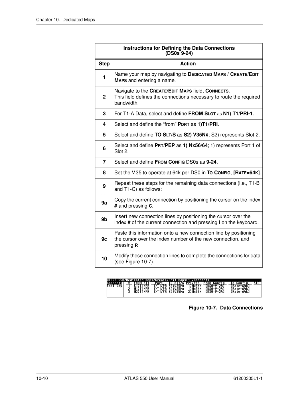
10 | Modify these connection lines to complete the connections for data | ||
(see Figure | |||
|
| ||
|
|
| |
|
|
| |
|
|
| |
Figure 10-7. Data Connections
ATLAS 550 User Manual |