Network Video Server User’s Guide
Rear Panel
Power |
| Ethernet | ||
|
|
|
|
|
|
|
|
|
|
|
|
|
|
|
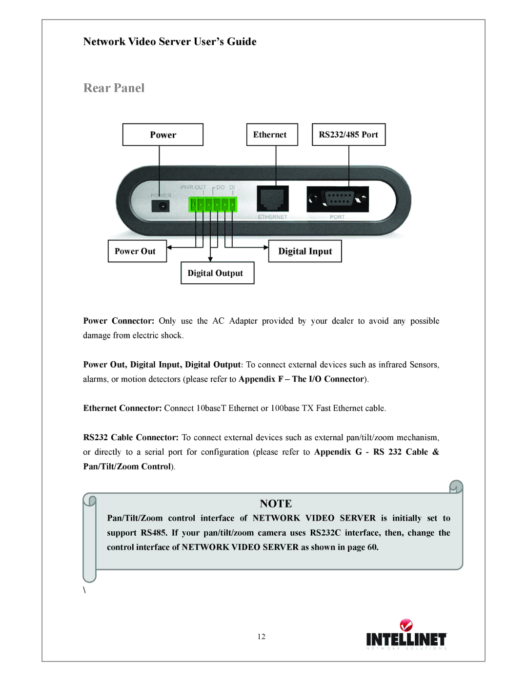
RS232/485 Port
Power Out
Digital Output
Digital Input
Power Connector: Only use the AC Adapter provided by your dealer to avoid any possible damage from electric shock.
Power Out, Digital Input, Digital Output: To connect external devices such as infrared Sensors, alarms, or motion detectors (please refer to Appendix F – The I/O Connector).
Ethernet Connector: Connect 10baseT Ethernet or 100base TX Fast Ethernet cable.
RS232 Cable Connector: To connect external devices such as external pan/tilt/zoom mechanism, or directly to a serial port for configuration (please refer to Appendix G - RS 232 Cable & Pan/Tilt/Zoom Control).
NOTE
Pan/Tilt/Zoom control interface of NETWORK VIDEO SERVER is initially set to support RS485. If your pan/tilt/zoom camera uses RS232C interface, then, change the control interface of NETWORK VIDEO SERVER as shown in page 60.
\
12
