Chapter 3 – Point Database
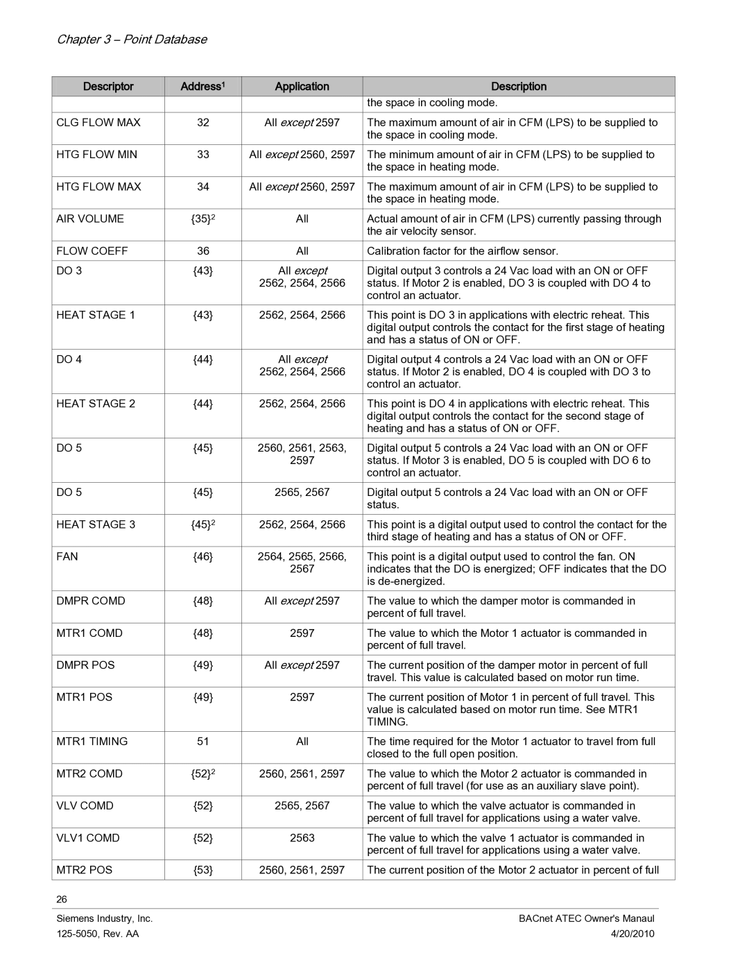
Descriptor | Address1 | Application | Description | |
|
|
| the space in cooling mode. | |
CLG FLOW MAX | 32 | All except 2597 | The maximum amount of air in CFM (LPS) to be supplied to | |
|
|
| the space in cooling mode. | |
HTG FLOW MIN | 33 | All except 2560, 2597 | The minimum amount of air in CFM (LPS) to be supplied to | |
|
|
| the space in heating mode. | |
HTG FLOW MAX | 34 | All except 2560, 2597 | The maximum amount of air in CFM (LPS) to be supplied to | |
|
|
| the space in heating mode. | |
AIR VOLUME | {35}2 | All | Actual amount of air in CFM (LPS) currently passing through | |
|
|
| the air velocity sensor. | |
FLOW COEFF | 36 | All | Calibration factor for the airflow sensor. | |
|
|
|
| |
DO 3 | {43} | All except | Digital output 3 controls a 24 Vac load with an ON or OFF | |
|
| 2562, 2564, 2566 | status. If Motor 2 is enabled, DO 3 is coupled with DO 4 to | |
|
|
| control an actuator. | |
HEAT STAGE 1 | {43} | 2562, 2564, 2566 | This point is DO 3 in applications with electric reheat. This | |
|
|
| digital output controls the contact for the first stage of heating | |
|
|
| and has a status of ON or OFF. | |
DO 4 | {44} | All except | Digital output 4 controls a 24 Vac load with an ON or OFF | |
|
| 2562, 2564, 2566 | status. If Motor 2 is enabled, DO 4 is coupled with DO 3 to | |
|
|
| control an actuator. | |
HEAT STAGE 2 | {44} | 2562, 2564, 2566 | This point is DO 4 in applications with electric reheat. This | |
|
|
| digital output controls the contact for the second stage of | |
|
|
| heating and has a status of ON or OFF. | |
DO 5 | {45} | 2560, 2561, 2563, | Digital output 5 controls a 24 Vac load with an ON or OFF | |
|
| 2597 | status. If Motor 3 is enabled, DO 5 is coupled with DO 6 to | |
|
|
| control an actuator. | |
DO 5 | {45} | 2565, 2567 | Digital output 5 controls a 24 Vac load with an ON or OFF | |
|
|
| status. | |
HEAT STAGE 3 | {45}2 | 2562, 2564, 2566 | This point is a digital output used to control the contact for the | |
|
|
| third stage of heating and has a status of ON or OFF. | |
FAN | {46} | 2564, 2565, 2566, | This point is a digital output used to control the fan. ON | |
|
| 2567 | indicates that the DO is energized; OFF indicates that the DO | |
|
|
| is | |
DMPR COMD | {48} | All except 2597 | The value to which the damper motor is commanded in | |
|
|
| percent of full travel. | |
MTR1 COMD | {48} | 2597 | The value to which the Motor 1 actuator is commanded in | |
|
|
| percent of full travel. | |
DMPR POS | {49} | All except 2597 | The current position of the damper motor in percent of full | |
|
|
| travel. This value is calculated based on motor run time. | |
MTR1 POS | {49} | 2597 | The current position of Motor 1 in percent of full travel. This | |
|
|
| value is calculated based on motor run time. See MTR1 | |
|
|
| TIMING. | |
MTR1 TIMING | 51 | All | The time required for the Motor 1 actuator to travel from full | |
|
|
| closed to the full open position. | |
MTR2 COMD | {52}2 | 2560, 2561, 2597 | The value to which the Motor 2 actuator is commanded in | |
|
|
| percent of full travel (for use as an auxiliary slave point). | |
VLV COMD | {52} | 2565, 2567 | The value to which the valve actuator is commanded in | |
|
|
| percent of full travel for applications using a water valve. | |
VLV1 COMD | {52} | 2563 | The value to which the valve 1 actuator is commanded in | |
|
|
| percent of full travel for applications using a water valve. | |
MTR2 POS | {53} | 2560, 2561, 2597 | The current position of the Motor 2 actuator in percent of full | |
|
|
|
|
|
26 |
|
|
|
|
|
|
|
|
|
Siemens Industry, Inc. |
|
| BACnet ATEC Owner's Manaul | |
|
| 4/20/2010 |
| |