|
|
| Chapter 3 – Point Database | |
|
|
|
| |
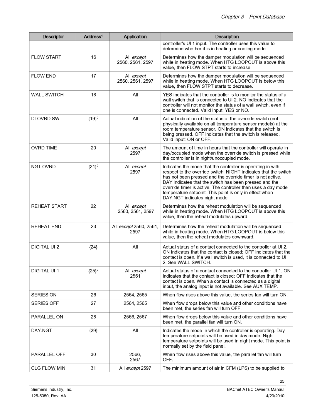
Descriptor | Address1 | Application | Description | |
|
|
| controller's Ul 1 input. The controller uses this value to | |
|
|
| determine whether it is in heating or cooling mode. | |
FLOW START | 16 | All except | Determines how the damper modulation will be sequenced | |
|
| 2560, 2561, 2597 | while in heating mode. When HTG LOOPOUT is above this | |
|
|
| value, then FLOW STPT starts to increase. | |
FLOW END | 17 | All except | Determines how the damper modulation will be sequenced | |
|
| 2560, 2561, 2597 | while in heating mode. When HTG LOOPOUT is below this | |
|
|
| value, then FLOW STPT starts to decrease. | |
WALL SWITCH | 18 | All | YES indicates that the controller is to monitor the status of a | |
|
|
| wall switch that is connected to UI 2. NO indicates that the | |
|
|
| controller will not monitor the status of a wall switch, even if | |
|
|
| one is connected. Valid input: YES or NO. | |
DI OVRD SW | {19}2 | All | Actual indication of the status of the override switch (not | |
|
|
| physically available on all temperature sensor models) at the | |
|
|
| room temperature sensor. ON indicates that the switch is | |
|
|
| being pressed. OFF indicates that the switch is released. | |
|
|
| Valid input: ON or OFF. | |
OVRD TIME | 20 | All except | The amount of time in hours that the controller will operate in | |
|
| 2597 | day/occupied mode when the override switch is pressed while | |
|
|
| the controller is in night/unoccupied mode. | |
NGT OVRD | {21}2 | All except | Indicates the mode that the controller is operating in with | |
|
| 2597 | respect to the override switch. NIGHT indicates that the switch | |
|
|
| has not been pressed and the override timer is not active. | |
|
|
| DAY indicates that the switch has been pressed and the | |
|
|
| override timer is active. The controller then uses a day mode | |
|
|
| temperature setpoint. This point is only in effect when | |
|
|
| DAY.NGT indicates night mode. | |
REHEAT START | 22 | All except | Determines how the reheat modulation will be sequenced | |
|
| 2560, 2561, 2597 | while in heating mode. When HTG LOOPOUT is above this | |
|
|
| value, then the reheat modulates upward. | |
|
|
|
| |
REHEAT END | 23 | All except 2560, 2561, | Determines how the reheat modulation will be sequenced | |
|
| 2597 | while in heating mode. When HTG LOOPOUT is below this | |
|
|
| value, then the reheat modulates downward. | |
|
|
|
| |
DIGITAL UI 2 | {24} | All | Actual status of a contact connected to the controller at UI 2. | |
|
|
| ON indicates that the contact is closed; OFF indicates that the | |
|
|
| contact is open. If a wall switch is used, it is connected to UI | |
|
|
| 2. See WALL SWITCH. | |
DIGITAL UI 1 | {25}2 | All except | Actual status of a contact connected to the controller UI 1. ON | |
|
| 2561 | indicates that the contact is closed; OFF indicates that the | |
|
|
| contact is open. When a contact is connected as a digital | |
|
|
| input, the analog input is not available. See AUX TEMP. | |
SERIES ON | 26 | 2564, 2565 | When flow rises above this value, the series fan will turn ON. | |
|
|
|
| |
SERIES OFF | 27 | 2564, 2565 | When flow drops below this value and other conditions have | |
|
|
| been met, the series fan will turn OFF. | |
PARALLEL ON | 28 | 2566, 2567 | When flow drops below this value and other conditions have | |
|
|
| been met, the parallel fan will turn ON. | |
DAY.NGT | {29} | All | Indicates the mode in which the controller is operating. Day | |
|
|
| temperature setpoints will be used in day mode. Night | |
|
|
| temperature setpoints will be used in night mode. This point is | |
|
|
| normally set by the field panel. | |
PARALLEL OFF | 30 | 2566, | When flow rises above this value, the parallel fan will turn | |
|
| 2567 | OFF. | |
CLG FLOW MIN | 31 | All except 2597 | The minimum amount of air in CFM (LPS) to be supplied to | |
|
|
|
|
|
|
|
| 25 |
|
|
|
|
|
|
Siemens Industry, Inc. |
|
| BACnet ATEC Owner's Manaul | |
|
| 4/20/2010 |
| |
Page 25
Image 25