Chapter 3 – Point Database
Descriptor | Address1 | Application | Description | |
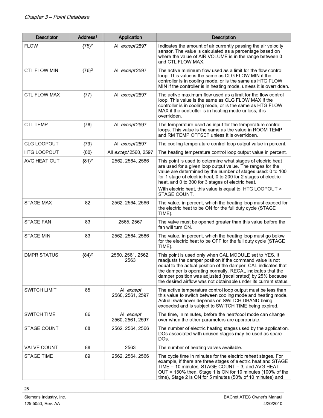
FLOW | {75}2 | All except 2597 | Indicates the amount of air currently passing the air velocity | |
|
|
| sensor. The value is calculated as a percentage based on | |
|
|
| where the value of AIR VOLUME is in the range between 0 | |
|
|
| and CTL FLOW MAX. | |
CTL FLOW MIN | {76}2 | All except 2597 | The active minimum flow used as a limit for the flow control | |
|
|
| loop. This value is the same as CLG FLOW MIN if the | |
|
|
| controller is in cooling mode, or is the same as HTG FLOW | |
|
|
| MIN if the controller is in heating mode, unless it is overridden. | |
CTL FLOW MAX | {77} | All except 2597 | The active maximum flow used as a limit for the flow control | |
|
|
| loop. This value is the same as CLG FLOW MAX if the | |
|
|
| controller is in cooling mode, or is the same as HTG FLOW | |
|
|
| MAX if the controller is in heating mode unless, it is | |
|
|
| overridden. | |
CTL TEMP | {78} | All except 2597 | The temperature used as input for the temperature control | |
|
|
| loops. This value is the same as the value in ROOM TEMP | |
|
|
| and RM TEMP OFFSET unless it is overridden. | |
CLG LOOPOUT | {79} | All except 2597 | The cooling temperature control loop output value in percent. | |
|
|
|
| |
HTG LOOPOUT | {80} | All except 2560, 2597 | The heating temperature control loop output value in percent. | |
|
|
|
| |
AVG HEAT OUT | {81}2 | 2562, 2564, 2566 | This point is used to determine what stages of electric heat | |
|
|
| are used for a given loop output value. The ranges for the | |
|
|
| value are determined by the number of stages used: 0 to 100 | |
|
|
| for 1 stage of electric heat, 0 to 200 for 2 stages of electric | |
|
|
| heat, and 0 to 300 for 3 stages of electric heat. | |
|
|
| With electric heat, this value is equal to: HTG LOOPOUT × | |
|
|
| STAGE COUNT. | |
STAGE MAX | 82 | 2562, 2564, 2566 | The value, in percent, which the heating loop must exceed for | |
|
|
| the electric heat to be ON for the full duty cycle (STAGE | |
|
|
| TIME). | |
STAGE FAN | 83 | 2565, 2567 | The valve must be opened greater than this value before the | |
|
|
| fan will turn ON. | |
STAGE MIN | 83 | 2562, 2564, 2566 | The value, in percent, which the heating loop must go below | |
|
|
| for the electric heat to be OFF for the full duty cycle (STAGE | |
|
|
| TIME). | |
DMPR STATUS | {84}2 | 2560, 2561, 2562, | This point is used only when CAL MODULE set to YES. It | |
|
| 2563 | readjusts the damper position if the command value is not | |
|
|
| equal to the actual position of the damper. CAL indicates that | |
|
|
| the damper is operating normally. RECAL indicates that the | |
|
|
| damper position was adjusted (recalibrated) by 25% because | |
|
|
| the desired airflow was not obtainable under its current status. | |
SWITCH LIMIT | 85 | All except | The active temperature control loop output must be less than | |
|
| 2560, 2561, 2597 | this value to switch between cooling mode and heating mode. | |
|
|
| Actual switchover depends on SWITCH DBAND being | |
|
|
| exceeded and is subject to SWITCH TIME being expired. | |
SWITCH TIME | 86 | All except | The time, in minutes, before the heat/cool mode can change | |
|
| 2560, 2561, 2597 | over when the other parameters are appropriate. | |
STAGE COUNT | 88 | 2562, 2564, 2566 | The number of electric heating stages used by the application. | |
|
|
| DOs associated with unused stages may be used as spare | |
|
|
| DOs. | |
VALVE COUNT | 88 | 2563 | The number of heating valves available. | |
|
|
|
| |
STAGE TIME | 89 | 2562, 2564, 2566 | The cycle time in minutes for the electric reheat stages. For | |
|
|
| example, if there are three stages of electric heat and STAGE | |
|
|
| TIME = 10 minutes, STAGE COUNT = 3, and AVG HEAT | |
|
|
| OUT = 150% then, Stage 1 is ON for 10 minutes (100% of the | |
|
|
| time), Stage 2 is ON for 5 minutes (50% of 10 minutes) and | |
28 |
|
|
|
|
|
|
|
|
|
Siemens Industry, Inc. |
|
| BACnet ATEC Owner's Manaul | |
|
| 4/20/2010 |
| |