|
|
| Chapter 3 – Point Database |
|
|
|
|
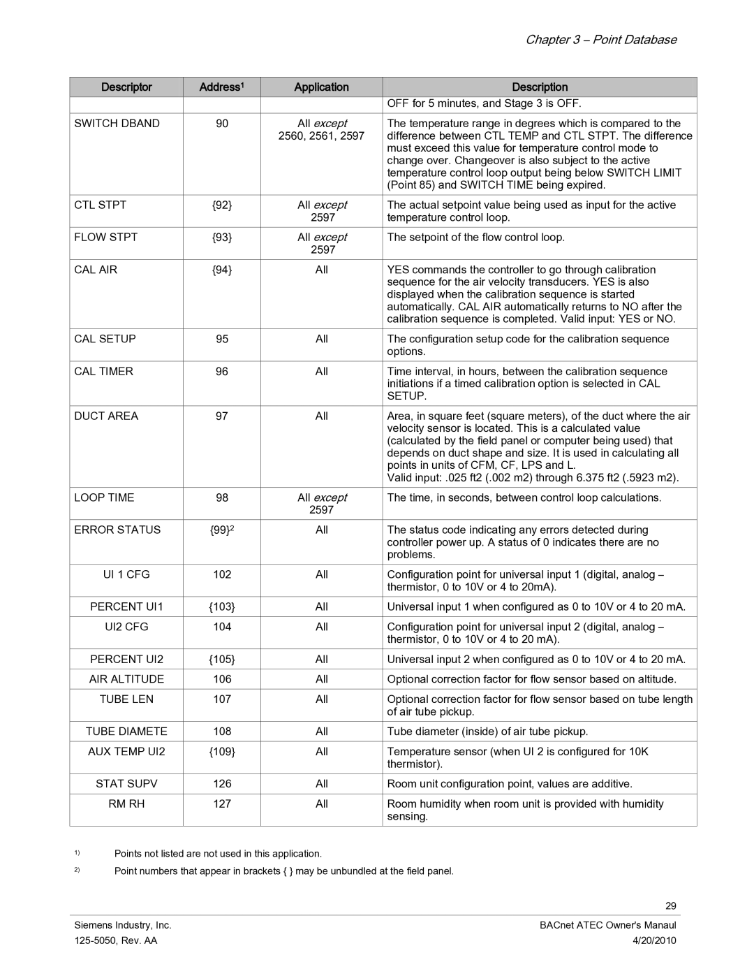
Descriptor | Address1 | Application | Description |
|
|
| OFF for 5 minutes, and Stage 3 is OFF. |
SWITCH DBAND | 90 | All except | The temperature range in degrees which is compared to the |
|
| 2560, 2561, 2597 | difference between CTL TEMP and CTL STPT. The difference |
|
|
| must exceed this value for temperature control mode to |
|
|
| change over. Changeover is also subject to the active |
|
|
| temperature control loop output being below SWITCH LIMIT |
|
|
| (Point 85) and SWITCH TIME being expired. |
CTL STPT | {92} | All except | The actual setpoint value being used as input for the active |
|
| 2597 | temperature control loop. |
FLOW STPT | {93} | All except | The setpoint of the flow control loop. |
|
| 2597 |
|
CAL AIR | {94} | All | YES commands the controller to go through calibration |
|
|
| sequence for the air velocity transducers. YES is also |
|
|
| displayed when the calibration sequence is started |
|
|
| automatically. CAL AIR automatically returns to NO after the |
|
|
| calibration sequence is completed. Valid input: YES or NO. |
CAL SETUP | 95 | All | The configuration setup code for the calibration sequence |
|
|
| options. |
CAL TIMER | 96 | All | Time interval, in hours, between the calibration sequence |
|
|
| initiations if a timed calibration option is selected in CAL |
|
|
| SETUP. |
DUCT AREA | 97 | All | Area, in square feet (square meters), of the duct where the air |
|
|
| velocity sensor is located. This is a calculated value |
|
|
| (calculated by the field panel or computer being used) that |
|
|
| depends on duct shape and size. It is used in calculating all |
|
|
| points in units of CFM, CF, LPS and L. |
|
|
| Valid input: .025 ft2 (.002 m2) through 6.375 ft2 (.5923 m2). |
LOOP TIME | 98 | All except | The time, in seconds, between control loop calculations. |
|
| 2597 |
|
ERROR STATUS | {99}2 | All | The status code indicating any errors detected during |
|
|
| controller power up. A status of 0 indicates there are no |
|
|
| problems. |
UI 1 CFG | 102 | All | Configuration point for universal input 1 (digital, analog – |
|
|
| thermistor, 0 to 10V or 4 to 20mA). |
PERCENT UI1 | {103} | All | Universal input 1 when configured as 0 to 10V or 4 to 20 mA. |
|
|
|
|
UI2 CFG | 104 | All | Configuration point for universal input 2 (digital, analog – |
|
|
| thermistor, 0 to 10V or 4 to 20 mA). |
PERCENT UI2 | {105} | All | Universal input 2 when configured as 0 to 10V or 4 to 20 mA. |
|
|
|
|
AIR ALTITUDE | 106 | All | Optional correction factor for flow sensor based on altitude. |
|
|
|
|
TUBE LEN | 107 | All | Optional correction factor for flow sensor based on tube length |
|
|
| of air tube pickup. |
TUBE DIAMETE | 108 | All | Tube diameter (inside) of air tube pickup. |
|
|
|
|
AUX TEMP UI2 | {109} | All | Temperature sensor (when UI 2 is configured for 10K |
|
|
| thermistor). |
STAT SUPV | 126 | All | Room unit configuration point, values are additive. |
|
|
|
|
RM RH | 127 | All | Room humidity when room unit is provided with humidity |
|
|
| sensing. |
1)
2)
Points not listed are not used in this application.
Point numbers that appear in brackets { } may be unbundled at the field panel.
29
Siemens Industry, Inc. | BACnet ATEC Owner's Manaul |
4/20/2010 |