Mounting
L5 ± 0.2
*) |
112 ± 0.5
Drill hole for screw fixings
M6/ ![]() 7
7
A1 ±1
*) |
L3 ± 1 | L3 ± 1 | 112 ± 0.5 |
|
| Pressure points |
|
| for clamps |
L2 +1 |
| 112 ±0.5 56 ±1 |
L1 +1
A2 ±1
Clamp with grub screws
Rz 120 (in gasket area)
Gasket area |
|
|
|
|
| L4 ± 0.2 |
|
|
|
| ||||||
|
|
|
|
|
|
|
| |||||||||
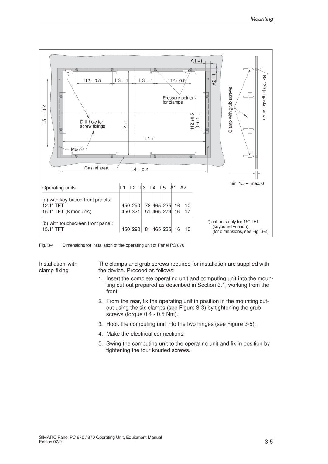
Operating units |
| L1 |
| L2 |
| L3 |
| L4 |
| L5 |
| A1 |
| A2 | ||
|
|
|
|
|
|
| ||||||||||
|
|
|
|
|
|
|
|
|
|
|
|
|
|
|
|
|
(a) with |
|
|
|
|
|
|
|
|
|
|
|
|
|
| ||
12.1º TFT |
| 450 |
| 290 |
| 78 |
| 465 |
| 235 |
| 16 |
| 10 | ||
15.1º TFT (8 modules) |
| 450 |
| 321 |
| 51 |
| 465 |
| 279 |
| 16 |
| 17 | ||
|
|
|
|
|
|
|
|
|
|
|
|
|
|
|
|
|
(b) with touchscreen front panel: |
|
|
|
|
|
|
|
|
|
|
|
|
|
| ||
15.1º TFT |
| 450 |
| 290 |
| 81 |
| 465 |
| 235 |
| 16 |
| 10 | ||
min. 1.5 ± max. 6
*)
(for dimensions, see Fig.
Fig. 3-4 Dimensions for installation of the operating unit of Panel PC 870
Installation with | The clamps and grub screws required for installation are supplied with | |
clamp fixing | the device. Proceed as follows: | |
| 1. | Insert the complete operating unit and computing unit into the moun- |
|
| ting |
|
| front. |
| 2. | From the rear, fix the operating unit in position in the mounting cut- |
|
| out using the six clamps (see Figure |
|
| screws (torque 0.4 - 0.5 Nm). |
| 3. | Hook the computing unit into the two hinges (see Figure |
| 4. | Make the electrical connections. |
| 5. | Swing the computing unit to the operating unit and fix in position by |
|
| tightening the four knurled screws. |
SIMATIC Panel PC 670 / 870 Operating Unit, Equipment Manual | |
Edition 07/01 |