| |
Type I, Style A | Description |
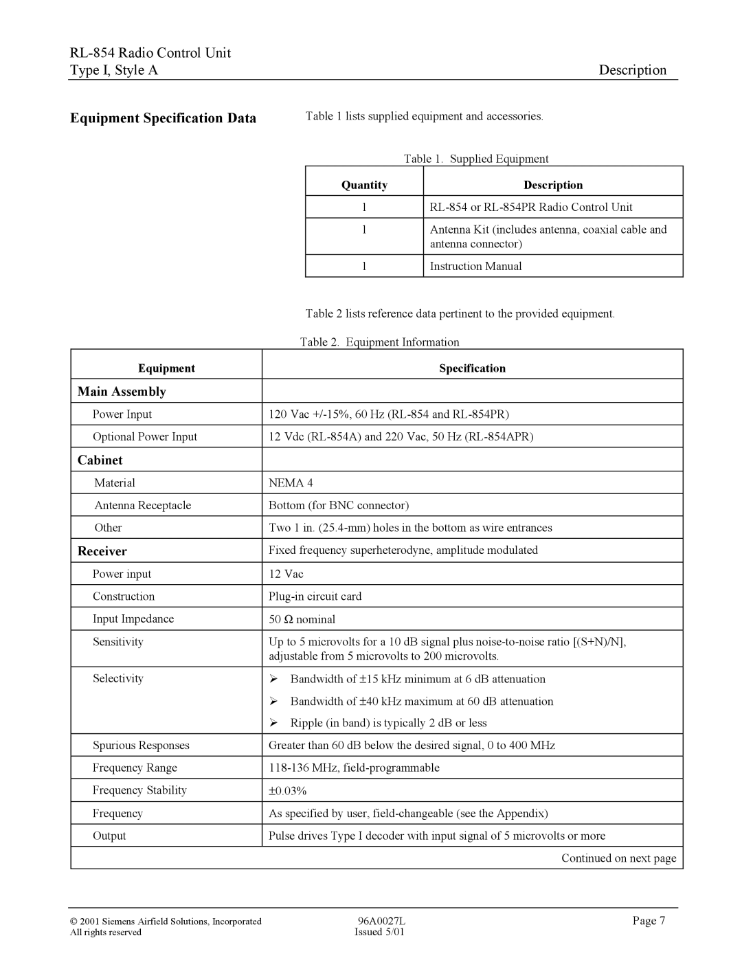
Equipment Specification Data
Table 1 lists supplied equipment and accessories.
| Table 1. Supplied Equipment |
Quantity | Description |
|
|
1 |
1Antenna Kit (includes antenna, coaxial cable and antenna connector)
1 | Instruction Manual |
| Table 2 lists reference data pertinent to the provided equipment. |
| Table 2. Equipment Information |
Equipment | Specification |
|
|
Main Assembly |
|
|
|
Power Input | 120 Vac |
|
|
Optional Power Input | 12 Vdc |
|
|
Cabinet |
|
|
|
Material | NEMA 4 |
|
|
Antenna Receptacle | Bottom (for BNC connector) |
|
|
Other | Two 1 in. |
|
|
Receiver | Fixed frequency superheterodyne, amplitude modulated |
|
|
Power input | 12 Vac |
|
|
Construction | |
|
|
Input Impedance | 50 Ω nominal |
|
|
Sensitivity | Up to 5 microvolts for a 10 dB signal plus |
| adjustable from 5 microvolts to 200 microvolts. |
|
|
Selectivity | Ø Bandwidth of ± 15 kHz minimum at 6 dB attenuation |
| Ø Bandwidth of ± 40 kHz maximum at 60 dB attenuation |
| Ø Ripple (in band) is typically 2 dB or less |
|
|
Spurious Responses | Greater than 60 dB below the desired signal, 0 to 400 MHz |
|
|
Frequency Range | |
|
|
Frequency Stability | ± 0.03% |
|
|
Frequency | As specified by user, |
|
|
Output | Pulse drives Type I decoder with input signal of 5 microvolts or more |
|
|
Continued on next page
2001 Siemens Airfield Solutions, Incorporated | 96A0027L | Page 7 |
All rights reserved | Issued 5/01 |
|