| |
Type I, Style A | Maintenance |
5. Maintenance
Introduction
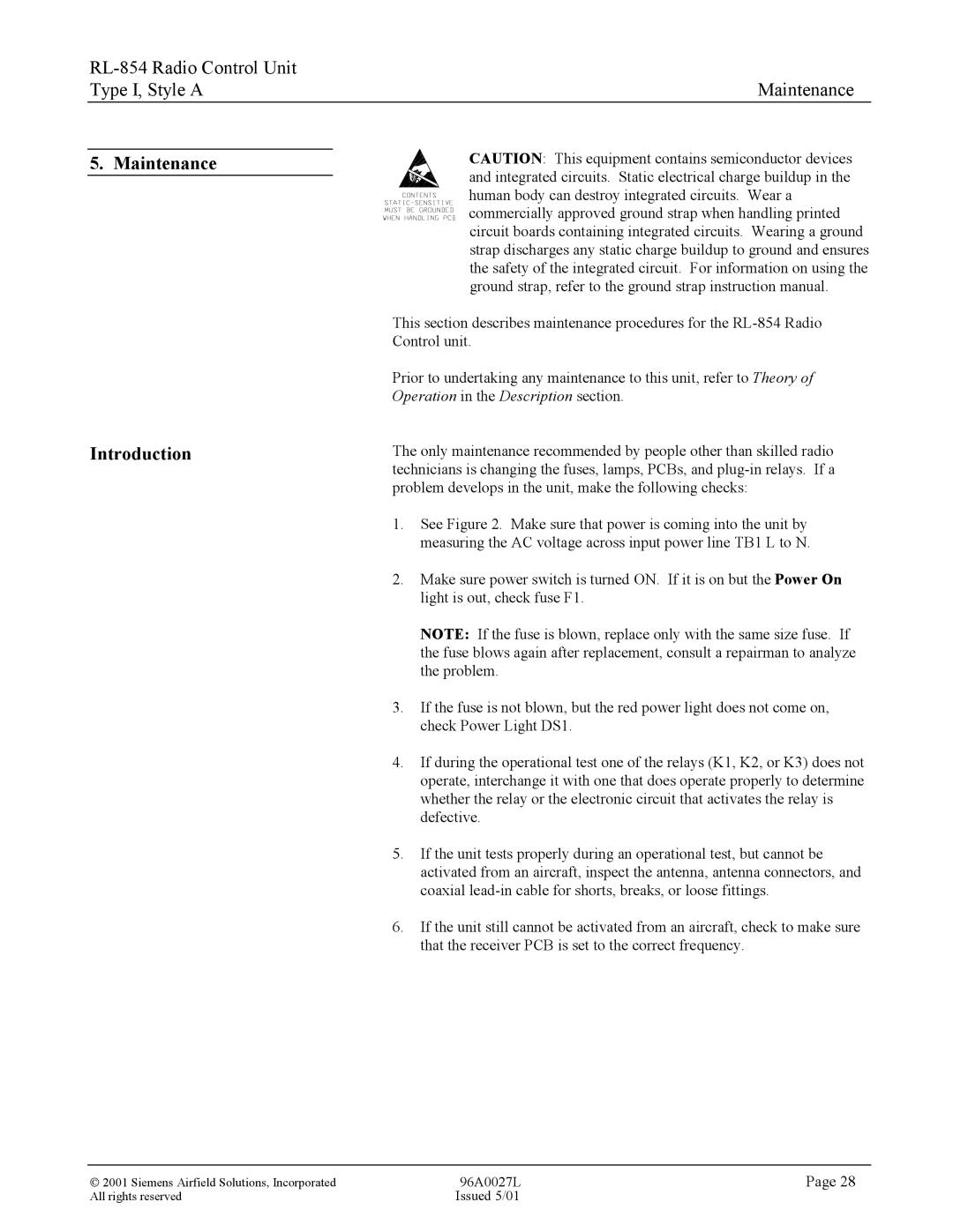
CAUTION: This equipment contains semiconductor devices and integrated circuits. Static electrical charge buildup in the human body can destroy integrated circuits. Wear a commercially approved ground strap when handling printed circuit boards containing integrated circuits. Wearing a ground strap discharges any static charge buildup to ground and ensures the safety of the integrated circuit. For information on using the ground strap, refer to the ground strap instruction manual.
This section describes maintenance procedures for the
Prior to undertaking any maintenance to this unit, refer to Theory of Operation in the Description section.
The only maintenance recommended by people other than skilled radio technicians is changing the fuses, lamps, PCBs, and
1.See Figure 2. Make sure that power is coming into the unit by measuring the AC voltage across input power line TB1 L to N.
2.Make sure power switch is turned ON. If it is on but the Power On light is out, check fuse F1.
NOTE: If the fuse is blown, replace only with the same size fuse. If the fuse blows again after replacement, consult a repairman to analyze the problem.
3.If the fuse is not blown, but the red power light does not come on, check Power Light DS1.
4.If during the operational test one of the relays (K1, K2, or K3) does not operate, interchange it with one that does operate properly to determine whether the relay or the electronic circuit that activates the relay is defective.
5.If the unit tests properly during an operational test, but cannot be activated from an aircraft, inspect the antenna, antenna connectors, and coaxial
6.If the unit still cannot be activated from an aircraft, check to make sure that the receiver PCB is set to the correct frequency.
2001 Siemens Airfield Solutions, Incorporated | 96A0027L | Page 28 |
All rights reserved | Issued 5/01 |
|
