| |
Type I, Style A | Maintenance |
Receiver Frequency Setting
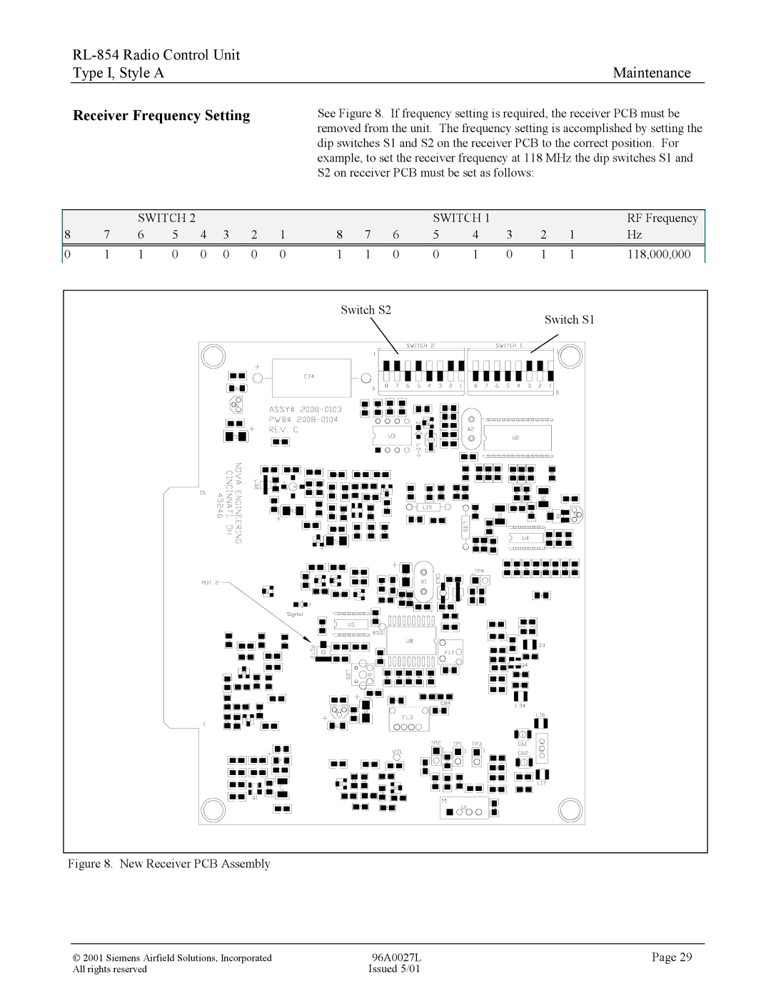
See Figure 8. If frequency setting is required, the receiver PCB must be removed from the unit. The frequency setting is accomplished by setting the dip switches S1 and S2 on the receiver PCB to the correct position. For example, to set the receiver frequency at 118 MHz the dip switches S1 and
S2 on receiver PCB must be set as follows:
|
| SWITCH 2 |
|
|
|
|
|
|
| SWITCH 1 |
|
|
| RF Frequency | ||
8 | 7 | 6 | 5 | 4 | 3 | 2 | 1 | 8 | 7 | 6 | 5 | 4 | 3 | 2 | 1 | Hz |
0 | 1 | 1 | 0 | 0 | 0 | 0 | 0 | 1 | 1 | 0 | 0 | 1 | 0 | 1 | 1 | 118,000,000 |
|
|
|
|
|
|
|
| Switch S2 |
|
|
|
| Switch S1 |
| ||
|
|
|
|
|
|
|
|
|
|
|
|
|
|
| ||
Figure 8. New Receiver PCB Assembly
2001 Siemens Airfield Solutions, Incorporated | 96A0027L | Page 29 |
All rights reserved | Issued 5/01 |
|