|
|
| SieMo S50037 Data Book PRELIMINARILY | ||
|
|
|
|
|
|
|
|
|
|
|
|
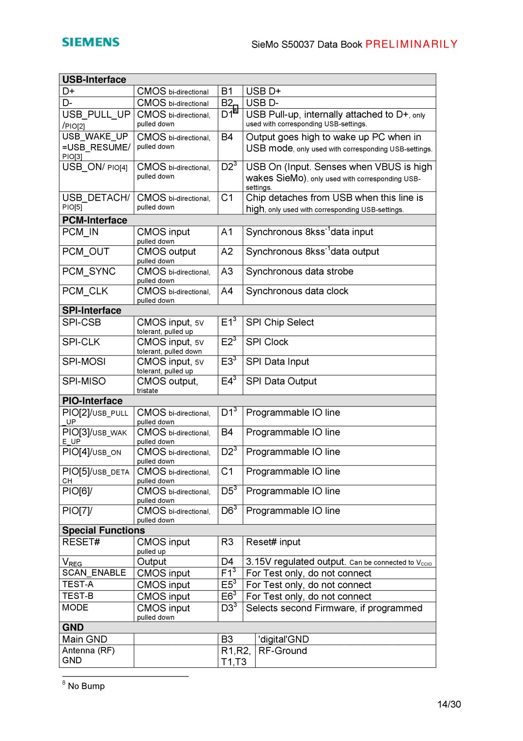
D+ | CMOS | B1 | USB D+ |
| |
D- | CMOS | B2 | USB D- |
| |
USB_PULL_UP | CMOS | D18 | USB |
| |
/PIO[2] | pulled down |
| used with corresponding |
| |
USB_WAKE_UP | CMOS | B4 | Output goes high to wake up PC when in |
| |
=USB_RESUME/ | pulled down |
| USB mode, only used with corresponding |
| |
PIO[3] |
|
|
|
|
|
USB_ON/ PIO[4] | CMOS | D23 | USB On (Input. Senses when VBUS is high |
| |
| pulled down |
| wakes SieMo), only used with corresponding USB- |
| |
|
|
| settings. |
| |
USB_DETACH/ | CMOS | C1 | Chip detaches from USB when this line is |
| |
PIO[5] | pulled down |
| high, only used with corresponding |
| |
|
|
|
|
|
|
PCM_IN | CMOS input | A1 | Synchronous |
| |
| pulled down |
|
|
|
|
PCM_OUT | CMOS output | A2 | Synchronous |
| |
| pulled down |
|
|
|
|
PCM_SYNC | CMOS | A3 | Synchronous data strobe |
| |
| pulled down |
|
|
|
|
PCM_CLK | CMOS | A4 | Synchronous data clock |
| |
| pulled down |
|
|
|
|
|
|
|
|
|
|
CMOS input, 5V | E13 | SPI Chip Select |
| ||
| tolerant, pulled up |
|
|
|
|
CMOS input, 5V | E23 | SPI Clock |
| ||
| tolerant, pulled down |
|
|
|
|
CMOS input, 5V | E33 | SPI Data Input |
| ||
| tolerant, pulled up |
|
|
|
|
CMOS output, | E43 | SPI Data Output |
| ||
| tristate |
|
|
|
|
|
|
|
|
|
|
PIO[2]/USB_PULL | CMOS | D13 | Programmable IO line |
| |
_UP | pulled down |
|
|
|
|
PIO[3]/USB_WAK | CMOS | B4 | Programmable IO line |
| |
E_UP | pulled down |
|
|
|
|
PIO[4]/USB_ON | CMOS | D23 | Programmable IO line |
| |
| pulled down |
|
|
|
|
PIO[5]/USB_DETA | CMOS | C1 | Programmable IO line |
| |
CH | pulled down |
|
|
|
|
PIO[6]/ | CMOS | D53 | Programmable IO line |
| |
| pulled down |
|
|
|
|
PIO[7]/ | CMOS | D63 | Programmable IO line |
| |
| pulled down |
|
|
|
|
Special Functions |
|
|
|
| |
RESET# | CMOS input | R3 | Reset# input |
| |
| pulled up |
|
|
|
|
VREG | Output | D4 | 3.15V regulated output. Can be connected to VCCIO |
| |
SCAN_ENABLE | CMOS input | F13 | For Test only, do not connect |
| |
CMOS input | E53 | For Test only, do not connect |
| ||
CMOS input | E63 | For Test only, do not connect |
| ||
MODE | CMOS input | D33 | Selects second Firmware, if programmed |
| |
| pulled down |
|
|
|
|
GND |
|
|
|
|
|
Main GND |
| B3 |
| 'digital'GND |
|
Antenna (RF) |
| R1,R2, |
| ||
GND |
| T1,T3 |
|
| |
8 No Bump
14/30
