S7 specifications
The Siemens S7 series represents a cornerstone in the realm of programmable logic controllers (PLCs), developed by Siemens, a leading company in industrial automation. Widely used across various industries, the S7 series offers robust solutions for controlling machinery and processes, thanks to its reliable performance, flexibility, and scalable architecture.One of the key features of Siemens S7 PLCs is the modularity of their design. Each system can be configured to meet specific application requirements due to the ability to mix various input/output modules, CPUs, and communication processors. This modular approach allows for the customization of systems to suit diverse automation tasks, providing end users with the adaptability required for modern manufacturing environments.
The S7 series encompasses several models, including the S7-1200, S7-300, and S7-1500. The S7-1200 is particularly suited for small to medium-sized applications, offering a compact design and integrated communication interfaces. In contrast, the S7-300 is designed for more extensive and complex control systems, making it ideal for large-scale industrial applications. The S7-1500 stands out with its advanced performance metrics, rich feature set, and high-speed processing capabilities, making it perfect for demanding applications that require real-time control and extensive data handling.
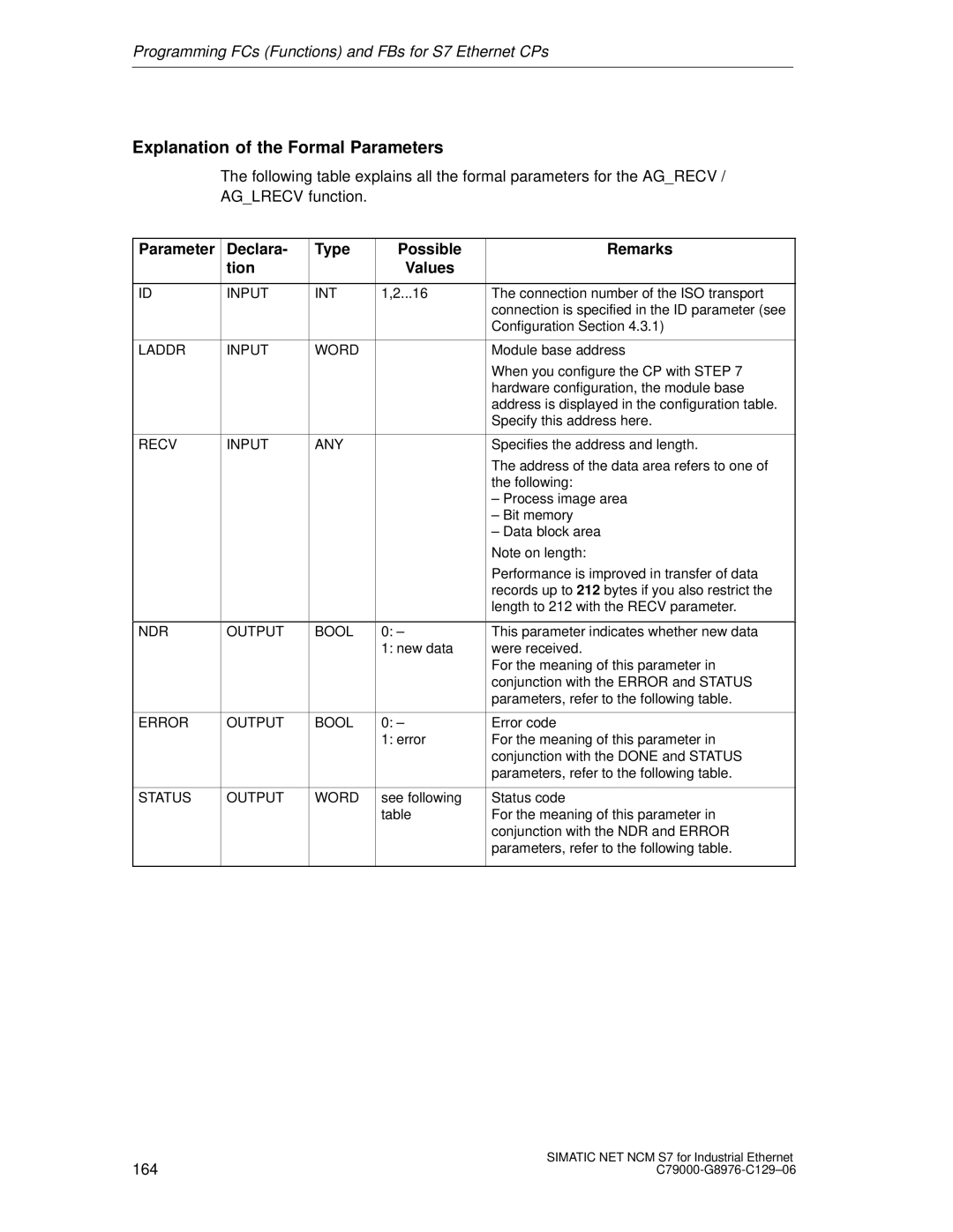
Siemens also emphasizes the importance of communication technologies within the S7 series. With options such as PROFINET, PROFIBUS, and EtherNet/IP, the S7 PLCs can seamlessly integrate into existing automation infrastructures, ensuring smooth data exchange between devices. The incorporation of web-based technologies and cloud connectivity further enables remote monitoring and control of systems, enhancing operational efficiency.
Another notable characteristic of Siemens S7 PLCs is the use of TIA Portal (Totally Integrated Automation Portal), an innovative software platform that simplifies the engineering process. TIA Portal allows users to program, configure, and diagnose their automation devices in a single environment, reducing setup times and improving productivity.
In conclusion, the Siemens S7 series stands out due to its modular design, range of models suitable for various applications, advanced communication technologies, and user-friendly programming software. This combination of features and characteristics makes S7 PLCs a preferred choice for industries seeking reliable and efficient automation solutions. As industrial demands continue to evolve, Siemens S7 PLCs remain at the forefront, adapting to technological advancements and setting benchmarks in the automation field.
