Instruction Manual
2. OPERATION
2.1General
When the Model 3100 Flame Detector is powered up, the microprocessor checks the configuration switch settings and configures the detector. The mi- croprocessor then runs a full series of self tests. After the self test process is complete and all tests are passed, the detector is ready to detect a fire.
All modes of operation are indicated by two LEDs located on the front of the detector. Normal Mode is indicated by a brief flash of the LEDs every 8 seconds. With the device in Normal Mode it is constantly monitoring the environment and ready to detect a fire.
When a fire is detected the flame detector will acti- vate the Fire Relay and turn on both LEDs. If the device is configured for “Latching” Mode the de- vice will remain in Alarm Mode until power is re- moved. In “Fire Following” Mode the Fire Relay will reset when the Fire Probability Algorithm de- termines there is no longer a fire.
The self test system is continuously monitoring the internal systems. When a fault is detected the Fault Relay is
will flash a code indicating the type of fault. A fault indication may mean the device is unable to detect a fire or that a device has become unreliable. (i.e. a “Voltage Low” fault) For most faults the detector will return to Normal Mode when the fault condi- tion is corrected.
The Model 3100 Series comes in several versions. The basic version
The
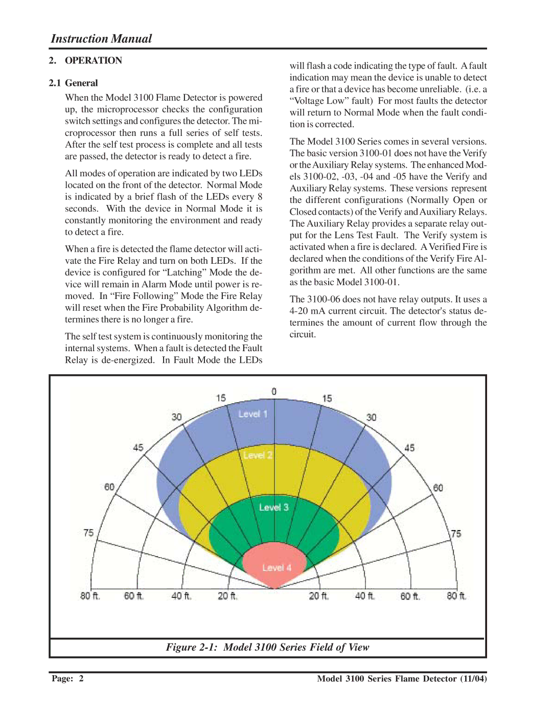
Figure 2-1: Model 3100 Series Field of View
Page: 2 | Model 3100 Series Flame Detector (11/04) |
