Instruction Manual
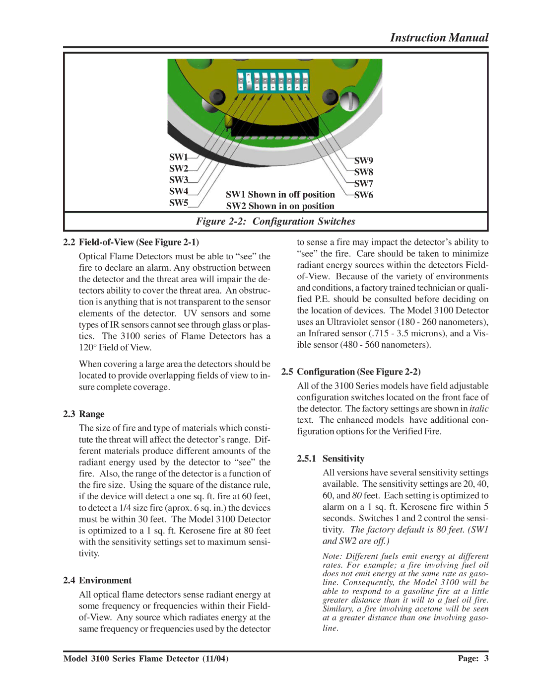
SW1
SW2
SW3
SW4
SW5
SW9
SW8
SW7 SW1 Shown in off position SW6 SW2 Shown in on position
Figure 2-2: Configuration Switches
2.2Field-of-View (See Figure 2-1)
Optical Flame Detectors must be able to “see” the fire to declare an alarm. Any obstruction between the detector and the threat area will impair the de- tectors ability to cover the threat area. An obstruc- tion is anything that is not transparent to the sensor elements of the detector. UV sensors and some types of IR sensors cannot see through glass or plas- tics. The 3100 series of Flame Detectors has a 120° Field of View.
When covering a large area the detectors should be located to provide overlapping fields of view to in- sure complete coverage.
2.3Range
The size of fire and type of materials which consti- tute the threat will affect the detector’s range. Dif- ferent materials produce different amounts of the radiant energy used by the detector to “see” the fire. Also, the range of the detector is a function of the fire size. Using the square of the distance rule, if the device will detect a one sq. ft. fire at 60 feet, to detect a 1/4 size fire (aprox. 6 sq. in.) the devices must be within 30 feet. The Model 3100 Detector is optimized to a 1 sq. ft. Kerosene fire at 80 feet with the sensitivity settings set to maximum sensi- tivity.
2.4Environment
All optical flame detectors sense radiant energy at some frequency or frequencies within their Field-
to sense a fire may impact the detector’s ability to “see” the fire. Care should be taken to minimize radiant energy sources within the detectors Field-
2.5Configuration (See Figure 2-2)
All of the 3100 Series models have field adjustable configuration switches located on the front face of the detector. The factory settings are shown in italic text. The enhanced models have additional con- figuration options for the Verified Fire.
2.5.1Sensitivity
All versions have several sensitivity settings available. The sensitivity settings are 20, 40, 60, and 80 feet. Each setting is optimized to alarm on a 1 sq. ft. Kerosene fire within 5 seconds. Switches 1 and 2 control the sensi- tivity. The factory default is 80 feet. (SW1 and SW2 are off.)
Note: Different fuels emit energy at different rates. For example; a fire involving fuel oil does not emit energy at the same rate as gaso- line. Consequently, the Model 3100 will be able to respond to a gasoline fire at a little greater distance than it will to a fuel oil fire. Similary, a fire involving acetone will be seen at a greater distance than one involving gaso- line.
Model 3100 Series Flame Detector (11/04) | Page: 3 |