Instruction Manual
LED 1 | LED 2 |
Mounting Screw
(2 locations)
Configuration Switches
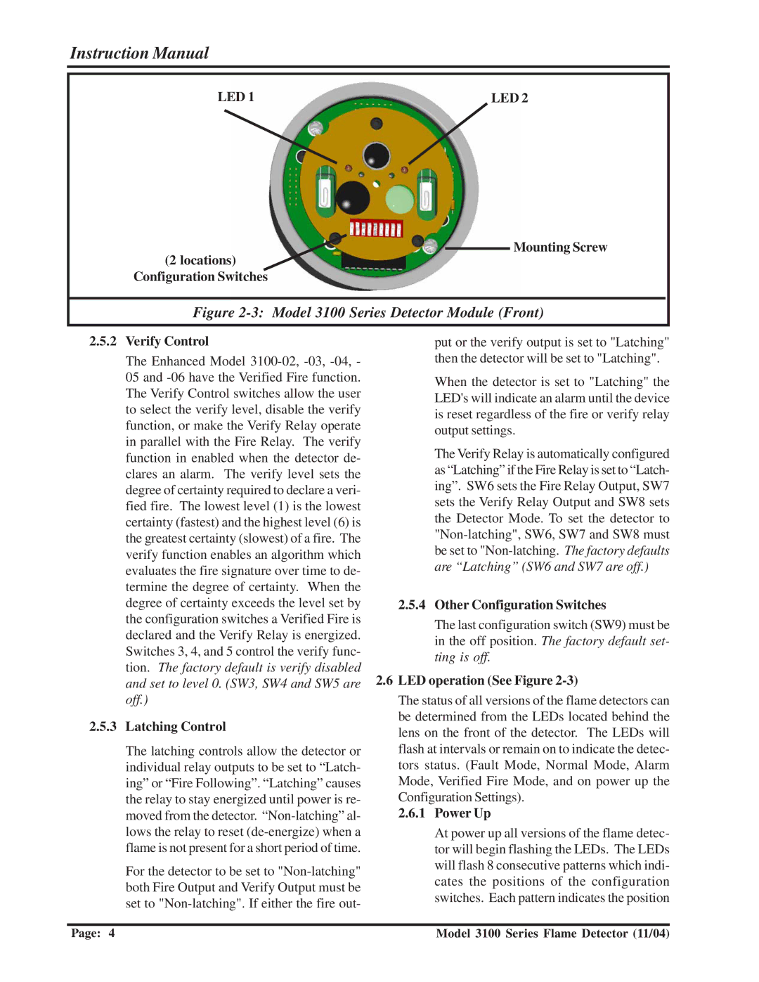
Figure 2-3: Model 3100 Series Detector Module (Front)
2.5.2Verify Control
The Enhanced Model
2.5.3Latching Control
The latching controls allow the detector or individual relay outputs to be set to “Latch- ing” or “Fire Following”. “Latching” causes the relay to stay energized until power is re- moved from the detector.
For the detector to be set to
put or the verify output is set to "Latching" then the detector will be set to "Latching".
When the detector is set to "Latching" the LED's will indicate an alarm until the device is reset regardless of the fire or verify relay output settings.
The Verify Relay is automatically configured as “Latching” if the Fire Relay is set to “Latch- ing”. SW6 sets the Fire Relay Output, SW7 sets the Verify Relay Output and SW8 sets the Detector Mode. To set the detector to
2.5.4Other Configuration Switches
The last configuration switch (SW9) must be in the off position. The factory default set- ting is off.
2.6LED operation (See Figure 2-3)
The status of all versions of the flame detectors can be determined from the LEDs located behind the lens on the front of the detector. The LEDs will flash at intervals or remain on to indicate the detec- tors status. (Fault Mode, Normal Mode, Alarm Mode, Verified Fire Mode, and on power up the Configuration Settings).
2.6.1Power Up
At power up all versions of the flame detec- tor will begin flashing the LEDs. The LEDs will flash 8 consecutive patterns which indi- cates the positions of the configuration switches. Each pattern indicates the position
Page: 4 | Model 3100 Series Flame Detector (11/04) |
