1. PRODUCT DESCRIPTION
1.1 Introduction
All versions of the Model 3100 Flame Detector Se- ries utilize Ultraviolet, Infrared and Visible spectrum to provide continuous and reliable flame detection. The microprocessor in the Model 3100 is config- ured with state-of-the-art fire algorithms and con- tinuously analyzes the data from the sensor array for individual intensity values, change of intensity values, relationship of intensity values and frequency signature correlations. Each algorithm is designed to recognize a different type of flame signature from the detectors while rejecting common false sources. When the conditions of any one of the several fire algorithms are met the Model 3100 declares a fire.
1.2 Fault Diagnostics
The micro-processor is also continuously perform- ing system tests looking for any faults which would impair its ability to accurately detect a flame and declare an alarm. The systems being tested include: input power, sensor circuits, relay circuits, and sev- eral other internal systems. The Model 3100 Flame Detector also performs a through the lens test of the sensor and lens systems. All faults are recorded in non-volatile memory and may be retrieved by a trained technician.
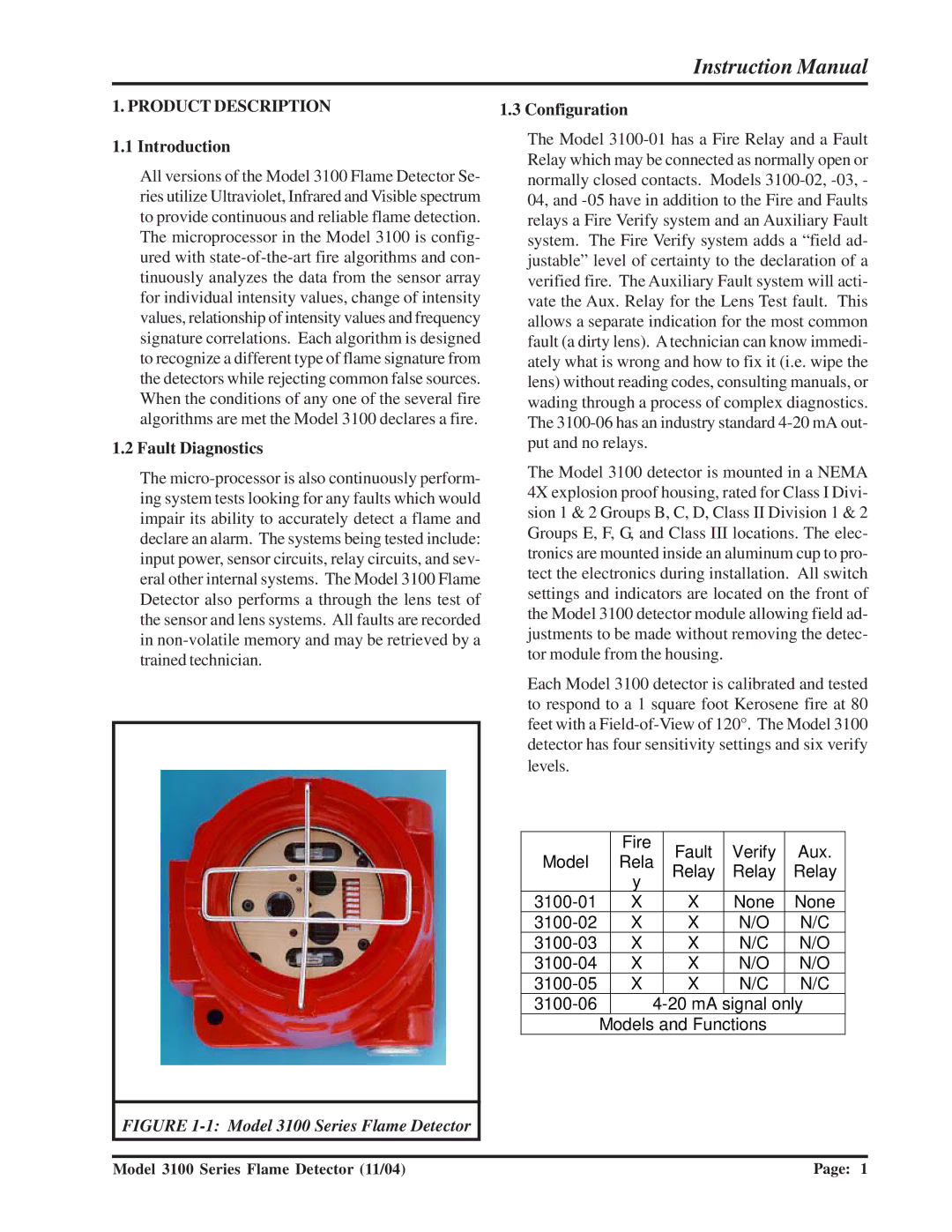
FIGURE 1-1: Model 3100 Series Flame Detector
1.3 Configuration
The Model 3100-01 has a Fire Relay and a Fault Relay which may be connected as normally open or normally closed contacts. Models 3100-02, -03, - 04, and -05 have in addition to the Fire and Faults relays a Fire Verify system and an Auxiliary Fault system. The Fire Verify system adds a “field ad- justable” level of certainty to the declaration of a verified fire. The Auxiliary Fault system will acti- vate the Aux. Relay for the Lens Test fault. This allows a separate indication for the most common fault (a dirty lens). A technician can know immedi- ately what is wrong and how to fix it (i.e. wipe the lens) without reading codes, consulting manuals, or wading through a process of complex diagnostics. The 3100-06 has an industry standard 4-20 mA out- put and no relays.
The Model 3100 detector is mounted in a NEMA 4X explosion proof housing, rated for Class I Divi- sion 1 & 2 Groups B, C, D, Class II Division 1 & 2 Groups E, F, G, and Class III locations. The elec- tronics are mounted inside an aluminum cup to pro- tect the electronics during installation. All switch settings and indicators are located on the front of the Model 3100 detector module allowing field ad- justments to be made without removing the detec- tor module from the housing.
Each Model 3100 detector is calibrated and tested to respond to a 1 square foot Kerosene fire at 80 feet with a Field-of-View of 120°. The Model 3100 detector has four sensitivity settings and six verify levels.
| | Fire | Fault | Verify | Aux. |
Model | | Rela |
| Relay | Relay | Relay |
| | y | | | |
3100-01 | | X | X | None | None |
3100-02 | | X | X | N/O | N/C |
3100-03 | | X | X | N/C | N/O |
3100-04 | | X | X | N/O | N/O |
3100-05 | | X | X | N/C | N/C |
3100-06 | | 4 | -20 mA signal only |
| | Models and Functions | |