Model
1.Remove the transmitter from the module housing by:
•Unscrew the two captive panel screws on the faceplate.
•Lift the transmitter out of the enclosure.
•Unplug the sensor cable from transmitter connector J1.
•Remove the sensor assembly from the enclosure hub.
2.Install the module enclosure onto the end of the supply conduit and/or bolt into position as required.
NOTE
When enclosure earth grounding is required for the installation a grounding lug is located in the base of the enclosure. Install the earth ground under the green ground screw.
4.4TRANSMITTER AND SENSOR INSTALLATION
When all
1.Install sensor assembly in the open hub on the module enclosure. The sensor assembly thread must be fully seated into the hub and tightened to maintain explosion proof assembly.
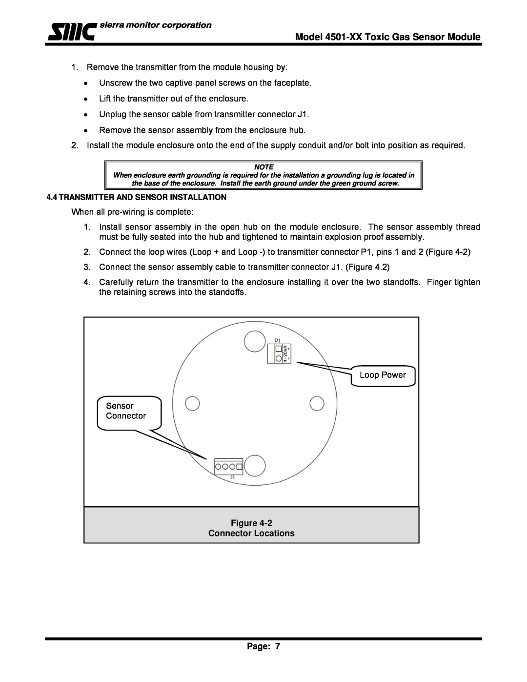
2.Connect the loop wires (Loop + and Loop
3.Connect the sensor assembly cable to transmitter connector J1. (Figure 4.2)
4.Carefully return the transmitter to the enclosure installing it over the two standoffs. Finger tighten the retaining screws into the standoffs.
Loop Power
Sensor
Connector
Figure 4-2
Connector Locations
Page: 7