SMC sierra monitor corporation | Sentry Instruction Manual - Version 6 |
1.Confirm that system power has been removed.
2.Remove the transmitter electronics board from the main housing and unplug the sensor harness from the transmitter electronics.
3.Unscrew the sensor housing from the bottom of the enclosure
4.Hold the sensor assembly so that the harness faces down and the sensor faces up. Unscrew and remove the round section of the housing from the hex section. Be careful not to lose the spacer washer which will be sitting on top of the exposed sensor.
5.Carefully pull the old sensor straight up from the socket.
6.Orient the new sensor so that the sensor pin labeled “C” faces the socket labeled “C” which is on the far side of the board from the vertical reed switch. The reed switch will slide into a hole on the side of the new sensor. Press the new sensor’s pins into the three sockets.
7.Carefully replace the cover on the sensor assembly including the spacer washer.
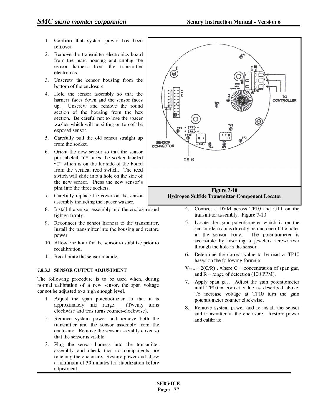
Figure
Hydrogen Sulfide Transmitter Component Locator
8.Install the sensor assembly into the enclosure and tighten firmly.
9.Reconnect the sensor harness to the transmitter, install the transmitter into the housing and restore power.
10.Allow one hour for the sensor to stabilize prior to recalibration.
11.Recalibrate the sensor module.
4.Connect a DVM across TP10 and GT1 on the transmitter assembly. Figure
5.Locate the gain potentiometer which is on the sensor electronics directly behind one of the holes in the sensor body. The potentiometer is accessible by inserting a jewelers screwdriver through the hole in the sensor.
6.Determine the correct value to be read at TP10 based on the following formula:
7.8.3.3 SENSOR OUTPUT ADJUSTMENT
The following procedure is to be used when, during normal calibration of a new sensor, the span voltage cannot be adjusted to a high enough level.
1.Adjust the span potentiometer so that it is approximately mid range. (Twenty turns clockwise and tens turns
2.Remove system power and remove both the transmitter and the sensor assembly from the enclosure. Remove the sensor assembly cover so that the sensor is visible.
3.Plug the sensor harness into the transmitter assembly and check that no components are touching the enclosure. Restore power and allow a minimum of 30 minutes for stabilization before adjustment.
VTP10 = 2(C/R) , where C = concentration of span gas, and R = range of detection (100 PPM).
7.Apply span gas. Adjust the gain potentiometer until TP10 = correct value as described above. To increase voltage at TP10 turn the gain potentiometer counter clockwise.
8.Remove system power and