SMC sierra monitor corporation | Sentry Instruction Manual - Version 6 | ||||
|
|
| |||
7.5 COMBUSTIBLE GAS SENSOR MODULE |
|
| |||
|
|
| |||
7.5.1 DESCRIPTION |
|
| |||
The Combustible Gas Module includes the sensor |
|
| |||
and electronic assembly installed in an explosion |
|
| |||
proof housing. The sensor screws into one hub of |
|
| |||
the enclosure and plugs into the bottom |
|
| |||
electronics card via a six pin connector. Cabling |
|
| |||
to the controller connects to a three pin spring |
|
| |||
loaded terminal strip. |
|
| |||
7.5.2 TROUBLE ANALYSIS |
|
| |||
Electrical adjustment, or replacement of the |
|
| |||
sensor will be necessary under the following |
|
| |||
conditions: |
|
| |||
| • Controller displays the following error |
|
| ||
| messages: |
|
| ||
| CHK BRIDGE VOLT |
|
| ||
| SENSOR FAILURE |
|
| ||
| LOW SENSITIVITY |
|
| ||
| • False readings or alarms are received |
|
| ||
| due to sensor inaccuracy. |
|
| ||
Warning: : During sensor adjustments the |
|
| |||
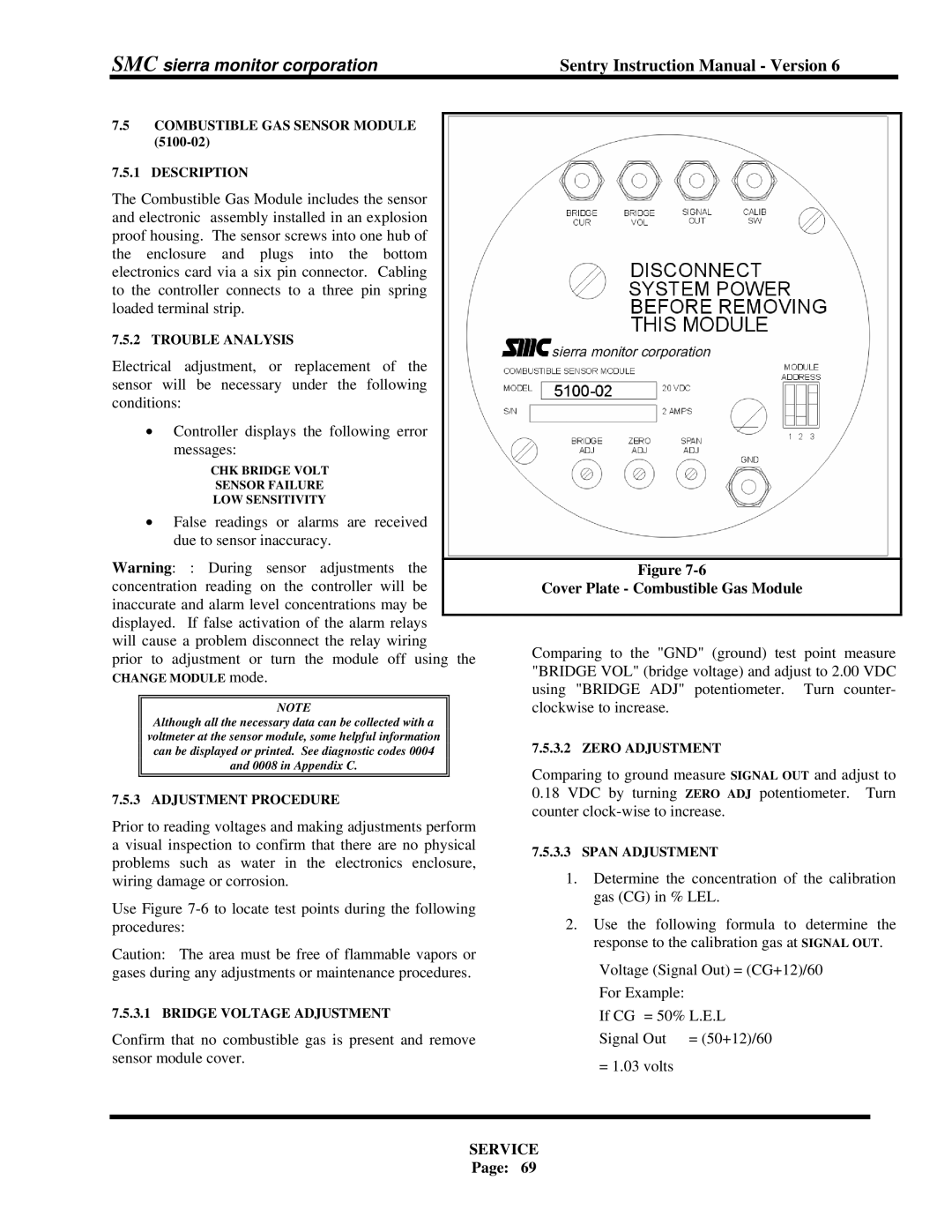
| Figure | ||||
concentration reading on the controller will be |
| Cover Plate - Combustible Gas Module | |||
inaccurate and alarm level concentrations may be |
|
| |||
displayed. If false activation of the alarm relays |
|
| |||
will cause a problem disconnect the relay wiring | Comparing to the "GND" (ground) test point measure | ||||
prior to adjustment or turn the module off using the | |||||
"BRIDGE VOL" (bridge voltage) and adjust to 2.00 VDC | |||||
CHANGE MODULE mode. | |||||
using "BRIDGE ADJ" potentiometer. Turn counter- | |||||
|
|
|
| ||
| NOTE |
| clockwise to increase. | ||
| Although all the necessary data can be collected with a |
|
| ||
| voltmeter at the sensor module, some helpful information |
| 7.5.3.2 ZERO ADJUSTMENT | ||
| can be displayed or printed. See diagnostic codes 0004 |
| |||
| and 0008 in Appendix C. |
| Comparing to ground measure SIGNAL OUT and adjust to | ||
|
|
|
| ||
|
|
|
| ||
7.5.3 ADJUSTMENT PROCEDURE | 0.18 VDC by turning ZERO ADJ potentiometer. Turn | ||||
counter | |||||
Prior to reading voltages and making adjustments perform | |||||
| |||||
a visual inspection to confirm that there are no physical | 7.5.3.3 SPAN ADJUSTMENT | ||||
problems such as water in the electronics enclosure, | |||||
1. Determine the concentration of the calibration | |||||
wiring damage or corrosion. | |||||
Use Figure | gas (CG) in % LEL. | ||||
2. Use the following formula to determine the | |||||
procedures: | |||||
Caution: The area must be free of flammable vapors or | response to the calibration gas at SIGNAL OUT. | ||||
Voltage (Signal Out) = (CG+12)/60 | |||||
gases during any adjustments or maintenance procedures. | |||||
|
|
|
| For Example: | |
7.5.3.1 BRIDGE VOLTAGE ADJUSTMENT
Confirm that no combustible gas is present and remove sensor module cover.
If CG = 50% L.E.L Signal Out = (50+12)/60
= 1.03 volts