SMC sierra monitor corporation | Sentry Instruction Manual - Version 6 |
7.8 HYDROGEN SULFIDE MODULE
7.8.1 DESCRIPTION
Model
The sensor assembly includes a reuseable housing and disposable electrochemical sensor. The assembly screws into one hub of the sensor module enclosure and plugs into the bottom electronics card via a six pin connector.
Cabling from the controller connects to a three pin spring loaded terminal strip on the electronics assembly.
7.8.2 TROUBLE ANALYSIS
Electrical adjustment, or replacement of the sensor will be necessary under the following conditions:
•Controller displays the following error messages
|
|
|
| SENSOR FAILURE |
|
|
|
|
|
|
|
|
|
| |||
|
|
|
| LOW SENSITIVITY |
|
|
|
|
|
|
|
|
|
| |||
| • |
|
|
|
|
|
|
|
| Figure |
|
|
| ||||
| False | readings | or alarms are received |
|
|
|
|
|
| ||||||||
|
|
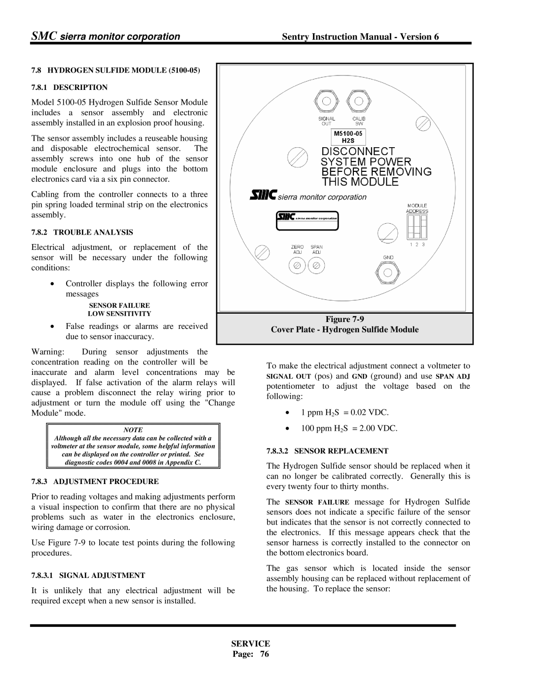
| Cover Plate - Hydrogen Sulfide Module |
|
| ||||||||||||
|
| due to sensor inaccuracy. |
|
|
|
|
|
|
| ||||||||
|
|
|
|
|
|
|
|
|
|
|
| ||||||
Warning: |
| During sensor | adjustments | the |
|
|
|
|
|
|
| ||||||
concentration reading on the | controller will | be |
| To make the electrical adjustment connect a voltmeter to | |||||||||||||
inaccurate | and | alarm | level | concentrations | may | be | |||||||||||
SIGNAL OUT (pos) and GND (ground) and use SPAN ADJ | |||||||||||||||||
displayed. | If false activation of | the alarm relays will | |||||||||||||||
potentiometer to adjust the voltage | based | on the | |||||||||||||||
cause a | problem disconnect | the | relay wiring prior | to | |||||||||||||
following: |
|
|
| ||||||||||||||
adjustment or turn the module off using the "Change |
|
|
| ||||||||||||||
• | 1 ppm H2S = 0.02 VDC. |
|
|
| |||||||||||||
Module" mode. |
|
|
|
|
|
|
|
|
|
|
| ||||||
|
|
|
|
|
|
|
|
|
|
| • | 100 ppm H2S = 2.00 VDC. |
|
|
| ||
|
|
|
|
| NOTE |
|
|
|
|
|
|
|
| ||||
| Although all the necessary data can be collected with a |
|
|
|
|
|
|
| |||||||||
| voltmeter at the sensor module, some helpful information |
|
| 7.8.3.2 | SENSOR REPLACEMENT |
|
|
| |||||||||
| can be displayed on the controller or printed. See |
|
|
|
|
| |||||||||||
|
| diagnostic codes 0004 and 0008 in Appendix C. |
|
| The Hydrogen Sulfide sensor should be replaced when it | ||||||||||||
|
|
|
|
|
|
|
|
|
|
|
| ||||||
7.8.3 ADJUSTMENT PROCEDURE |
|
|
|
| can no longer be calibrated correctly. | Generally this is | |||||||||||
|
|
|
| every twenty four to thirty months. |
|
|
| ||||||||||
Prior to reading voltages and making adjustments perform |
|
|
| ||||||||||||||
The SENSOR FAILURE message for Hydrogen | Sulfide | ||||||||||||||||
a visual inspection to confirm that there are no physical | |||||||||||||||||
sensors does not indicate a specific failure of the sensor | |||||||||||||||||
problems |
| such | as water in | the | electronics | enclosure, | |||||||||||
| but indicates that the sensor is not correctly connected to | ||||||||||||||||
wiring damage or corrosion. |
|
|
|
|
|
| |||||||||||
|
|
|
|
|
| the electronics. If this message appears check that the | |||||||||||
|
|
|
|
|
|
|
|
|
|
|
| ||||||
Use Figure | sensor harness is correctly installed to the connector on | ||||||||||||||||
procedures. |
|
|
|
|
|
|
|
| the bottom electronics board. |
|
|
| |||||
7.8.3.1 SIGNAL ADJUSTMENT |
|
|
|
|
| The gas sensor which is located inside the sensor | |||||||||||
|
|
|
|
| assembly housing can be replaced without replacement of | ||||||||||||
It is unlikely that any electrical adjustment will be | the housing. To replace the sensor: |
|
|
| |||||||||||||
required except when a new sensor is installed. |
|
|
|
|
|
|
|
|
| ||||||||
SERVICE
Page: 76
