SMC sierra monitor corporation | Sentry Instruction Manual - Version 6 |
7.6 OXYGEN MODULE
7.6.1 DESCRIPTION
The Oxygen Module includes the electronic assembly installed in an explosion proof housing and the electrochemical sensor connected to one hub of the enclosure. Cabling from the controller connects to a three pin spring loaded terminal strip.
7.6.2 TROUBLE ANALYSIS
Electrical adjustment, or replacement of the sensor will be necessary under the following conditions:
•Controller displays the following error messages:
CHANGE SENSOR
SENSOR FAILURE
REPLACE SENSOR
•False readings or alarms are received due to sensor inaccuracy.
Warning: During | sensor | adjustments | the |
|
concentration reading on the controller will be |
| |||
inaccurate and alarm level concentrations may be | Figure | |||
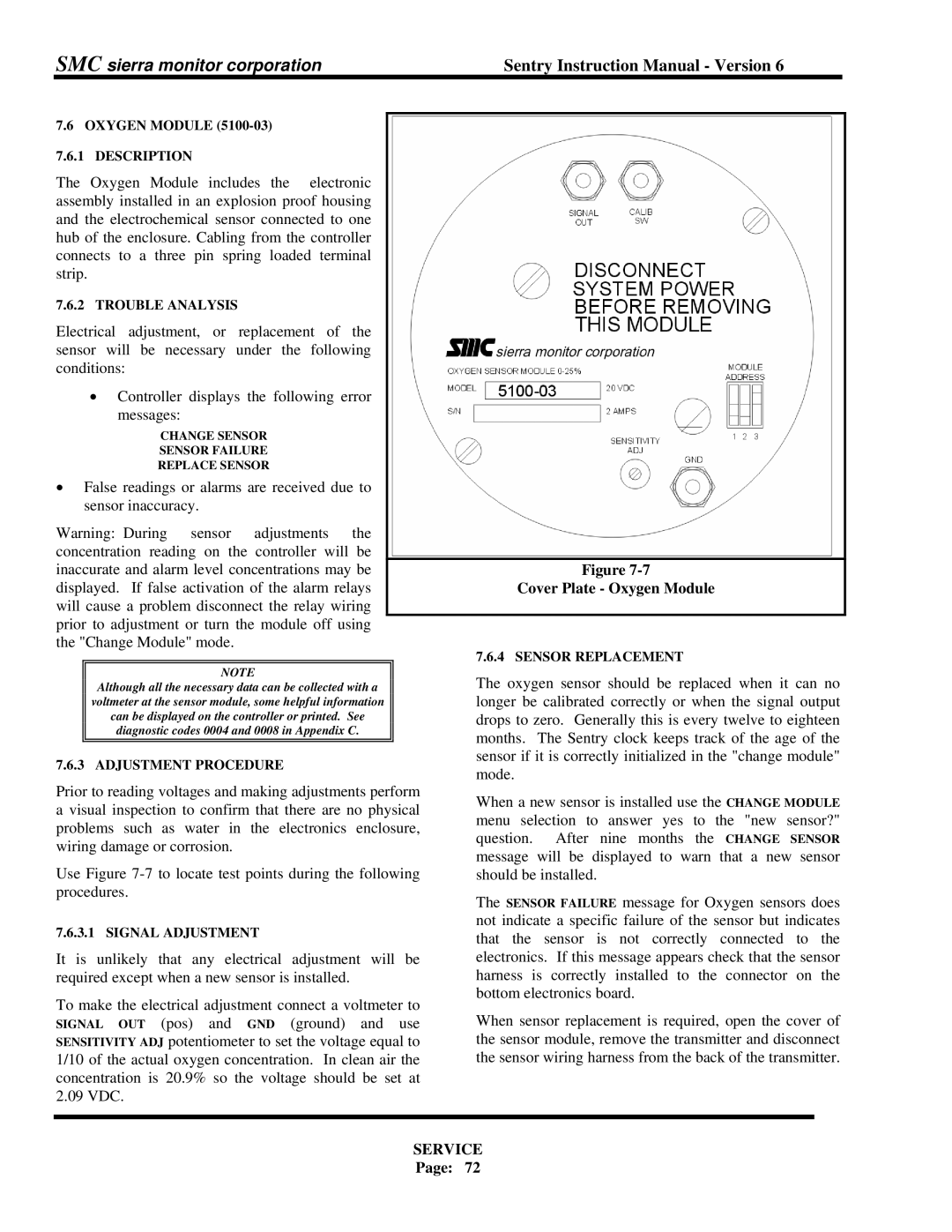
displayed. If false activation of the alarm relays | Cover Plate - Oxygen Module | |||
will cause a problem disconnect the relay wiring |
| |||
prior to adjustment or turn the module off using |
| |||
the "Change Module" mode.
|
|
| 7.6.4 SENSOR REPLACEMENT |
|
|
|
| ||
| NOTE |
| The oxygen sensor should be replaced when it can no | ||||||
| Although all the necessary data can be collected with a |
| |||||||
| voltmeter at the sensor module, some helpful information |
| longer be calibrated correctly or when the signal output | ||||||
| can be displayed on the controller or printed. See |
| drops to zero. Generally this is every twelve to eighteen | ||||||
| diagnostic codes 0004 and 0008 in Appendix C. |
| months. The Sentry clock keeps track of the age of the | ||||||
|
|
| |||||||
|
|
| |||||||
7.6.3 ADJUSTMENT PROCEDURE | sensor if it is correctly initialized in the "change module" | ||||||||
mode. |
|
|
|
|
| ||||
Prior to reading voltages and making adjustments perform |
|
|
|
|
| ||||
When a new sensor is installed use the CHANGE MODULE | |||||||||
a visual inspection to confirm that there are no physical | |||||||||
menu selection to | answer yes | to | the "new | sensor?" | |||||
problems such as water in the electronics enclosure, | |||||||||
question. After | nine months | the | CHANGE | SENSOR | |||||
wiring damage or corrosion. | |||||||||
message will be displayed to warn that a new sensor | |||||||||
Use Figure | |||||||||
should be installed. |
|
|
|
|
| ||||
procedures. | The SENSOR FAILURE message for Oxygen sensors does | ||||||||
|
|
| |||||||
7.6.3.1 SIGNAL ADJUSTMENT | not indicate a specific failure of the sensor but indicates | ||||||||
that the sensor is not correctly connected to the | |||||||||
|
|
| |||||||
It is unlikely that any electrical adjustment will be | electronics. If this message appears check that the sensor | ||||||||
required except when a new sensor is installed. | harness is correctly installed to the connector on the | ||||||||
To make the electrical adjustment connect a voltmeter to | bottom electronics board. |
|
|
|
| ||||
When sensor replacement is required, open the cover of | |||||||||
SIGNAL OUT (pos) and GND (ground) and use | |||||||||
SENSITIVITY ADJ potentiometer to set the voltage equal to | the sensor module, remove the transmitter and disconnect | ||||||||
1/10 of the actual oxygen concentration. In clean air the | the sensor wiring harness from the back of the transmitter. | ||||||||
concentration is 20.9% so the voltage should be set at |
|
|
|
|
|
| |||
2.09 VDC. |
|
|
|
|
|
| |||
|
|
|
|
|
|
|
| ||
|
| SERVICE |
|
|
|
|
| ||
|
| Page: | 72 |
|
|
|
|
| |
