Specifications
•Power
Interface Port Pin-Outs
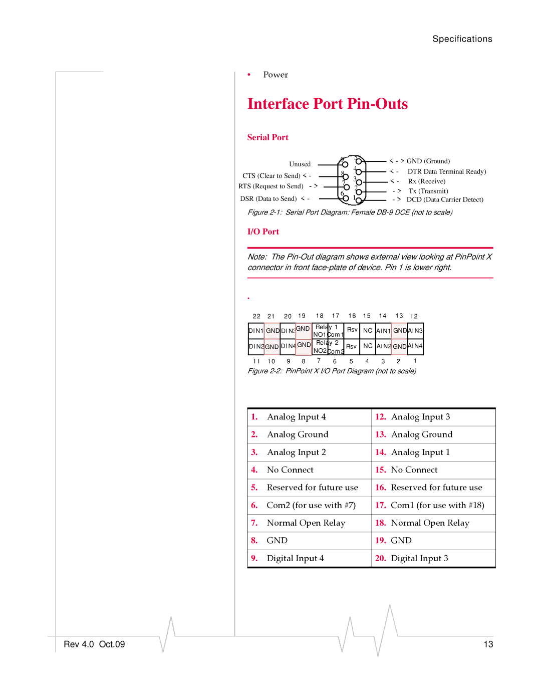
Serial Port
Unused CTS (Clear to Send) < -
RTS (Request to Send) - > DSR (Data to Send) < -
9 |
| 5 |
|
|
| < - > GND (Ground) | ||
| 4 |
|
|
| ||||
8 |
|
|
|
| < - DTR Data Terminal Ready) | |||
| 3 |
|
|
| ||||
7 |
|
|
| < - | Rx (Receive) | |||
|
|
| 2 |
|
| - > | Tx (Transmit) | |
6 |
|
|
| |||||
| 1 |
| ||||||
|
|
|
|
|
| - > DCD (Data Carrier Detect) | ||
|
|
|
|
|
| |||
|
|
|
|
|
| |||
Figure 2-1: Serial Port Diagram: Female DB-9 DCE (not to scale)
I/O Port
Note: The
.
22 | 21 | 20 | 19 | 18 | 17 | 16 | 15 | 14 | 13 | 12 | |
|
|
|
|
|
|
|
|
|
|
| |
DIN1 | GND | DIN3 | GND | Relay | 1 | Rsv | NC | AIN1 | GNDAIN3 | ||
|
|
|
| NO1Com1 |
|
|
|
|
| ||
DIN2GND | DIN4 | GND | Relay 2 | Rsv | NC | AIN2 | GND | AIN4 | |||
|
|
|
| NO2Com2 |
|
|
|
|
| ||
11 | 10 | 9 | 8 | 7 | 6 | 5 | 4 | 3 | 2 | 1 | |
Figure 2-2: PinPoint X I/O Port Diagram (not to scale)
1. | Analog Input 4 | 12. | Analog Input 3 |
|
|
|
|
2. | Analog Ground | 13. | Analog Ground |
|
|
|
|
3. | Analog Input 2 | 14. | Analog Input 1 |
|
|
|
|
4. | No Connect | 15. | No Connect |
|
|
|
|
5. | Reserved for future use | 16. | Reserved for future use |
|
|
|
|
6. | Com2 (for use with #7) | 17. | Com1 (for use with #18) |
|
|
|
|
7. | Normal Open Relay | 18. | Normal Open Relay |
|
|
|
|
8. | GND | 19. | GND |
|
|
|
|
9. | Digital Input 4 | 20. | Digital Input 3 |
|
|
|
|
|
|
|
|
|
|
|
Rev 4.0 Oct.09 |
|
|
|
|
| 13 |
|
|
|