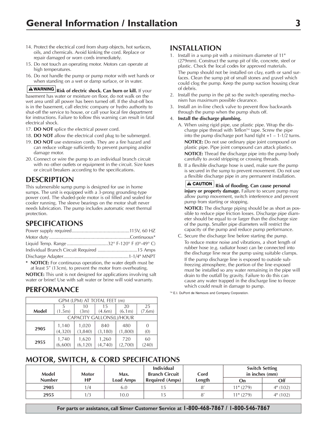
Simer Pumps 2905 General Information / Installation, Description, Specifications, Performance

Models: 2905 2955

1 16
Download 16 pages 18.62 Kb
Page 3
Image 3
General Information / Installation

General Information / Installation

3

14.Protect the electrical cord from sharp objects, hot surfaces, oils, and chemicals. Avoid kinking the cord. Replace or repair damaged or worn cords immediately.

15.Do not touch an operating motor. Motors can operate at high temperatures.

16.Do not handle the pump or pump motor with wet hands or when standing on a wet or damp surface, or in water.

DESCRIPTIONSPECIFICATIONSPERFORMANCEINSTALLATIONMOTOR, SWITCH, & CORD SPECIFICATIONSManual backgroundManual backgroundManual backgroundManual background Risk of electric shock. Can burn or kill. If your basement has water or moisture on floor, do not walk on the wet area until all power has been turned off. If the shut-off box is in the basement, call electric company or hydro authority to shut-off the service to house, or call your local fire department for instructions. Failure to follow this warning can result in fatal electrical shock.

17.DO NOT splice the electrical power cord.

18.DO NOT allow the electrical cord plug to be submerged.

19.DO NOT use extension cords. They are a fire hazard and can reduce voltage sufficiently to prevent pumping and/or damage motor.

20.Connect or wire the pump to an individual branch circuit with no other outlets or equipment in the circuit. Size fuses or circuit breakers according to the specifications.

DESCRIPTION

This submersible sump pump is designed for use in home sumps. The unit is equipped with a 3-prong grounding-type power cord. The shaded-pole motor is oil filled and sealed for cooler running. The sleeve bearings on the motor shaft never needs lubrication. The pump includes automatic reset thermal protection.

SPECIFICATIONS

Power supply required

115V, 60 HZ

Motor duty

Continuous*

Liquid Temp. Range

32° F-120° F (0°-49° C)

Individual Branch Circuit Required

15 Amps

Discharge Adapter

1-1/4" MNPT

*NOTICE: For continuous operation, the water depth must be at least 5” (13cm), to prevent the motor from overheating.

NOTICE: This unit is not designed for applications involving salt water or brine! Use with salt water or brine will void warranty.

PERFORMANCE

GPM (LPM) AT TOTAL FEET (m)

Model

5

10

15

20

25

(1.5m)

(3m)

(4.6m)

(6.1m)

(7.6m)


CAPACITY GALLONS(L)/HOUR


2905

1,140

1,020

840

480

0

(4,320)

(3,840)

(3,180)

(1,800)

(0)


2955

1,740

1,620

1,260

720

60

(6,600)

(6,120)

(4,740)

(2,700)

(240)


INSTALLATION

1.Install in a sump pit with a minimum diameter of 11" (279mm). Construct the sump pit of tile, concrete, steel or plastic. Check the local codes for approved materials.

The pump should not be installed on clay, earth or sand sur- faces. Clean the sump pit of small stones and gravel which could clog the pump. Keep the pump suction housing clear of debris.

2.Install the pump in the pit so the switch operating mecha- nism has maximum possible clearance.

3.Install an in-line check valve to prevent flow backwards through the pump when the pump shuts off.

4.Install the discharge plumbing.

A.When using rigid pipe, use plastic pipe. Wrap the dis- charge pipe thread with TeflonTM tape. Screw the pipe into the pump discharge port hand tight +1 – 1-1/2 turns.

NOTICE: Do not use ordinary pipe joint compound on plastic pipe. Pipe joint compound can attack plastics.

NOTICE: Thread the discharge pipe into the pump body carefully to avoid stripping or crossing threads.

B.If a flexible discharge hose is used, make sure the pump is secured in the sump to prevent movement. Do not use a flexible discharge pipe in any permanent installation.

Manual backgroundManual backgroundManual backgroundManual backgroundManual backgroundManual backgroundManual backgroundManual backgroundManual backgroundManual background Risk of flooding. Can cause personal injury or property damage. Failure to secure pump may allow pump movement, switch interference and prevent pump from starting or stopping.

NOTICE: The discharge piping should be as short as pos- sible to reduce pipe friction losses. Discharge pipe diam- eter should be equal to or larger than the discharge size of the pump. Smaller pipe diameters will restrict the capacity of the pump and reduce pump performance.

C.Secure the discharge line before starting the pump.

To reduce motor noise and vibrations, a short length of rubber hose (e.g. radiator hose) can be connected into the discharge line near the pump using suitable clamps.

If the pump discharge line is exposed to outside sub- freezing atmosphere, the portion of the line exposed must be installed so any water remaining in the pipe will drain to the outfall by gravity. Failure to do this can cause any water trapped in the discharge line to freeze which could result in damage to pump.

TM E.I. DuPont de Nemours and Company Corporation.

MOTOR, SWITCH, & CORD SPECIFICATIONS


Individual


Switch Setting

Model

Motor

Max.

Branch Circuit

Cord

in inches (mm)

Number

HP

Load Amps

Required (Amps)

Length

On

Off

2905

1/4

6.0

15

8’

11" (279)

4" (102)

2955

1/3

10.0

15

8’

11" (279)

4" (102)


For parts or assistance, call Simer Customer Service at 1-800-468-7867 /1-800-546-7867

Page 3
Image 3
Simer Pumps 2905, 2955 owner manual General Information / Installation, Description, Specifications, Performance