B-200A, B-120A specifications
Slant/Fin is a recognized leader in the heating industry, particularly known for its impressive range of high-quality boilers. Among their offerings, the Slant/Fin B-120A and B-200A models stand out due to their efficiency and advanced features. These boilers are designed for residential and light commercial applications, providing reliable heating solutions for various environments.The B-120A model boasts a robust output of 120,000 BTUs per hour, making it suitable for slightly larger homes or spaces that require significant heating capacity. In contrast, the B-200A model delivers an impressive 200,000 BTUs per hour, catering to even larger sites where consistent and powerful heating is essential. Both models are designed with high-efficiency ratings, ensuring lower energy costs and reduced environmental impact.
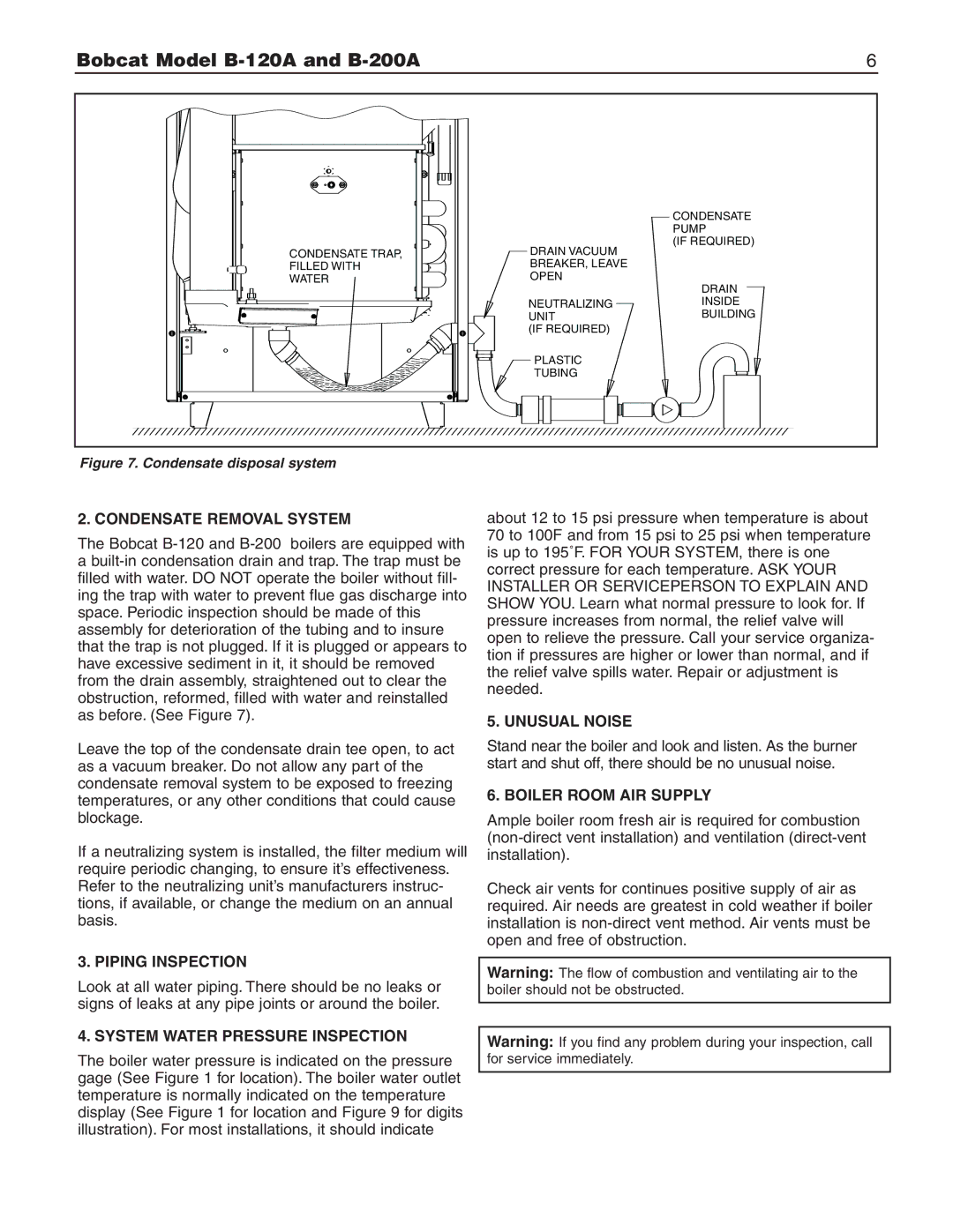
One of the key features of the Slant/Fin B series is the advanced cast-iron design. This construction allows for excellent thermal conductivity, providing even heating and maximizing the lifespan of the equipment. Cast iron is known for its ability to retain heat, which means that once heated, the boiler continues to produce warmth even as it cycles down, optimizing fuel usage.
The B-120A and B-200A are also equipped with an innovative electronic ignition system, enhancing their efficiency and reliability. This feature eliminates the need for a standing pilot light, leading to reduced energy usage and maintenance requirements. Both models are designed with ease of installation in mind, featuring a user-friendly layout that allows for straightforward hook-up to existing heating systems.
In terms of technology, Slant/Fin incorporates a variety of advanced components to enhance the performance of the B-120A and B-200A models. They feature multi-functional control systems that allow users to program their heating needs efficiently. Furthermore, the boilers come with an integrated pump that optimizes system operation and supports efficient water circulation, ensuring that heat is distributed evenly throughout the space.
Another characteristic appreciated by users is the noise level; both models operate quietly, minimizing disruption in residential environments. The maintenance of these boilers is also simplified due to their design, with accessible components allowing for easy servicing and cleaning.
In conclusion, the Slant/Fin B-120A and B-200A boilers exemplify a blend of efficiency, durability, and advanced technology. With their robust heating capacity, user-friendly features, and ease of maintenance, these models are an excellent choice for anyone looking to invest in reliable heating solutions for their home or light commercial space.