VICTORY | 13 |
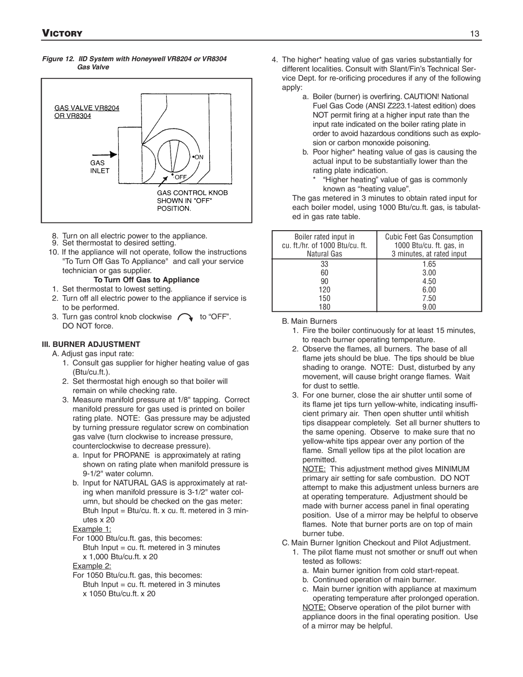
Figure 12. IID System with Honeywell VR8204 or VR8304 Gas Valve
4.The higher* heating value of gas varies substantially for different localities. Consult with Slant/Fin’s Technical Ser- vice Dept. for
a.Boiler (burner) is overfiring. CAUTION! National Fuel Gas Code (ANSI
b.Poor higher* heating value of gas is causing the actual input to be substantially lower than the rating plate indication.
*“Higher heating” value of gas is commonly
known as “heating value”.
The gas metered in 3 minutes to obtain rated input for each boiler model, using 1000 Btu/cu.ft. gas, is tabulat- ed in gas rate table.
8.Turn on all electric power to the appliance.
9.Set thermostat to desired setting.
10. If the appliance will not operate, follow the instructions
"To Turn Off Gas To Appliance" and call your service technicianToTurngas OffsupplierGas. to Appliance
1.Set thermostat to lowest setting.
2.Turn off all electric power to the appliance if service is
to be performed. |
|
|
3. Turn gas control knob clockwise |
| to “OFF”. |
DO NOT force. |
|
|
III. BURNER ADJUSTMENT |
|
|
A. Adjust gas input rate:
1. Consult gas supplier for higher heating value of gas (Btu/cu.ft.).
2. Set thermostat high enough so that boiler will remain on while checking rate.
3. Measure manifold pressure at 1/8" tapping. Correct manifold pressure for gas used is printed on boiler rating plate. NOTE: Gas pressure may be adjusted by turning pressure regulator screw on combination gas valve (turn clockwise to increase pressure, counterclockwise to decrease pressure).
a. Input for PROPANE is approximately at rating shown on rating plate when manifold pressure is
b. Input for NATURAL GAS is approximately at rat- ing when manifold pressure is
Btuh Input = Btu/cu. ft. x cu. ft. metered in 3 min- utes x 20
Example 1:
For 1000 Btu/cu.ft. gas, this becomes: Btuh Input = cu. ft. metered in 3 minutes x 1,000 Btu/cu.ft. x 20
Example 2:
For 1050 Btu/cu.ft. gas, this becomes: Btuh Input = cu. ft. metered in 3 minutes x 1050 Btu/cu.ft. x 20
Boiler rated input in | Cubic Feet Gas Consumption |
cu. ft./hr. of 1000 Btu/cu. ft. | 1000 Btu/cu. ft. gas, in |
Natural Gas | 3 minutes, at rated input |
33 | 1.65 |
60 | 3.00 |
90 | 4.50 |
120 | 6.00 |
150 | 7.50 |
180 | 9.00 |
B. Main Burners
1.Fire the boiler continuously for at least 15 minutes, to reach burner operating temperature.
2.Observe the flames, all burners. The base of all flame jets should be blue. The tips should be blue shading to orange. NOTE: Dust, disturbed by any movement, will cause bright orange flames. Wait for dust to settle.
3.For one burner, close the air shutter until some of its flame jet tips turn
NOTE: This adjustment method gives MINIMUM primary air setting for safe combustion. DO NOT attempt to make this adjustment unless burners are at operating temperature. Adjustment should be made with burner access panel in final operating position. Use of a mirror may be helpful to observe flames. Note that burner ports are on top of main burner tube.
C.Main Burner Ignition Checkout and Pilot Adjustment.
1.The pilot flame must not smother or snuff out when tested as follows:
a.Main burner ignition from cold
b.Continued operation of main burner.
c.Main burner ignition with appliance at maximum operating temperature after prolonged operation.
NOTE: Observe operation of the pilot burner with appliance doors in the final operating position. Use of a mirror may be helpful.