VICTORY | 15 |
burners as described on page 13.
*To clean burners run a clean flue brush up the tube until all foreign matter is removed.
IV. SAFETY CHECK FOR CONTROL SYSTEM
1.Remove Control Cover
To remove control cover, remove the two sheet metal screws in the top of the top cover. (See figure 13.) Tilt complete control cover away from boiler and lift up until it clears the bottom angle bracket. To replace the cover, reverse procedure. Be sure that the tab on the bottom of the cover body enters the slot in the bottom angle bracket. CAUTION: The boiler should not be operated with cover off except during certain control checkouts.
2.High Limit Control Test
Set thermostat high enough for boiler water temperature to reach high limit control setting. When this temperature is reached, the high limit switch should open and the main gas valve should close automatically. If the high limit does not operate to close the main gas valve, the valve, the high limit or the wiring is faulty. Repair or replace immediately.
3.Gas Valve Safety Shutdown Test
For boilers equipped with Honeywell S8600 intermittent pilot systems, with main burners firing, disconnect the ignition cable from the S8600 IGNITOR BOX. The gas valve should shut off the main burners.
If the gas valve fails to shut off the main burners when the test is performed, replace the gas valve.
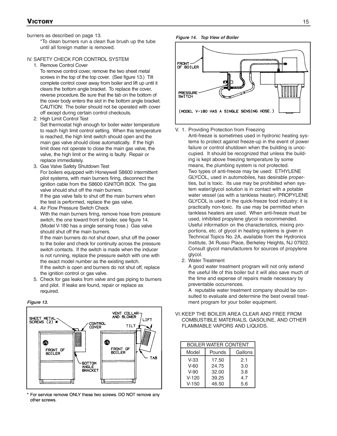
4.Air Flow Pressure Switch Check
With the main burners firing, remove hose from pressure switch, the one toward front of boiler, see figure 14. (Model
If the main burners do not shut down, shut off the power to the boiler and check for continuity across the pressure switch contacts. If the switch is made when the inducer is not running, replace the pressure switch with one with the exact model number as the existing switch.
If the switch is open and burners do not shut off, replace the ignition control or gas valve.
5.Check for gas leaks from valve and gas piping to burners and pilot. If leaks are found, repair or replace as required.
Figure 13.
Figure 14. Top View of Boiler
V. 1. Providing Protection from Freezing
Two types of
2.Water Treatment
A good water treatment program will not only extend the useful life of this boiler but it will also save much of the time and expense of repairs made necessary by preventable occurrences.
A reputable water treatment company should be con- sulted to evaluate and determine the best overall treat- ment program for your boiler equipment.
VI. KEEP THE BOILER AREA CLEAR AND FREE FROM COMBUSTIBLE MATERIALS, GASOLINE, AND OTHER FLAMMABLE VAPORS AND LIQUIDS.
BOILER WATER CONTENT
Model | Pounds | Gallons |
|
17.50 | 2.1 |
| |
24.75 | 3.0 |
| |
32.00 | 3.8 |
| |
39.25 | 4.7 |
| |
46.50 | 5.6 |
| |
|
|
|
|
*For service remove ONLY these two screws. DO NOT remove any other screws.