Manuals
/
Slant/Fin
/
Household Appliance
/
Boiler
Slant/Fin
V-33, V-180 Victory, Installation Requirements, Natural Gas Fired Boiler Location
Models:
V-33
V-180
1
3
20
20
Download
20 pages
37.3 Kb
1
2
3
4
5
6
7
8
Install
Wiring Diagrams
Electrical Controls And Wiring
Maintenance
Iii. Burner Adjustment
Safety
Page 3
Image 3
Page 2
Page 4
Page 3
Image 3
Page 2
Page 4
Contents
HOT WATER MODELS V-33THROUGH
Victory
VICTORY
Figure 1. Left End View
Figure 2. Front View
Figure 3. Right End View
BOILER FOUNDATION
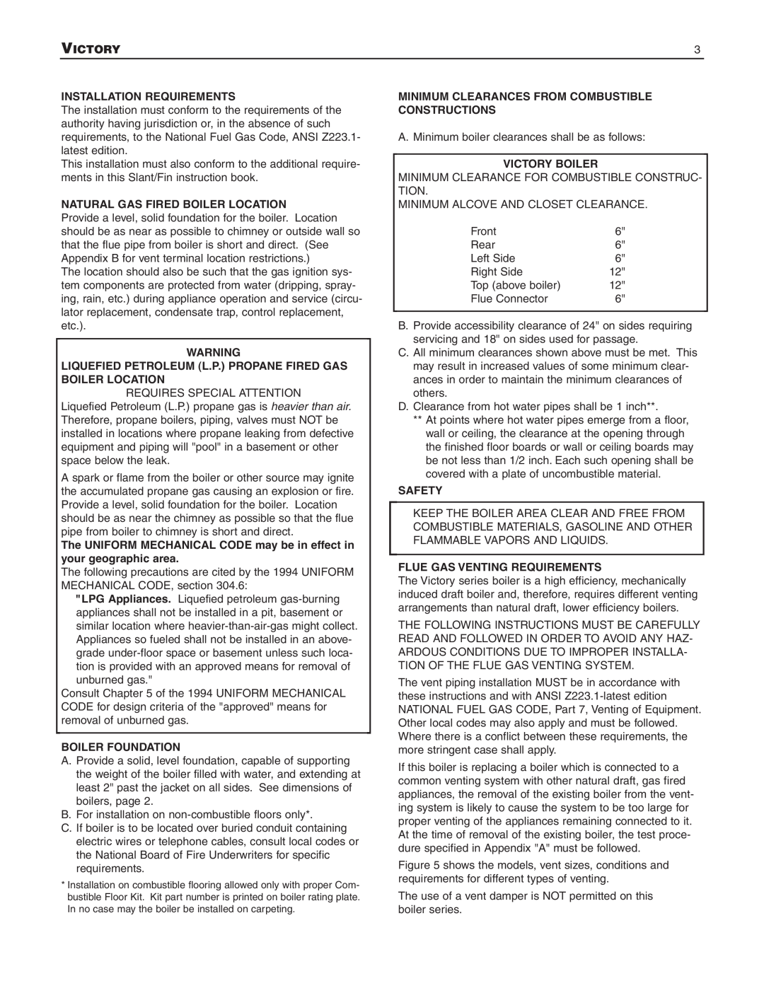
INSTALLATION REQUIREMENTS
VICTORY
NATURAL GAS FIRED BOILER LOCATION
Reference Table No
VICTORY
Figure 4. Vent Sealing Instructions
NATURAL DRAFT CHIMNEY
VICTORY
Model/Vent Size
Requirements
All vent connector joints must be LIQUID tight
Figure 6a
ALL ITEMS SHOWN BELOW ARE REQUIRED
Horizontal Venting 3 IN. All Victory Models
Horizontal Venting 3 IN. All Victory Models
VICTORY
VICTORY
Vertical Venting 3 IN. All Victory Models
ELECTRICAL CONTROLS AND WIRING
VICTORY
BOILER ROOM AIR SUPPLY AND VENTILATION
I. FILLING AND VENTING WATER SYSTEMS
SAFETY INFORMATION
VICTORY
OPERATING INSTRUCTIONS, BASIC
VICTORY
III. BURNER ADJUSTMENT
VICTORY
CARE AND MAINTENANCE
burners as described on page
Drain Requirements
VICTORY
APPENDIX A
APPENDIX B Vent System Location and Condensation
Sequence of Operations
Wiring Diagrams
TERMINALS
Pump Zoning system using R845 Relay
One R-845Aneeded for each circulator
COMBINATION CONTROLS WITH T TV Z
GENERAL TROUBLESHOOTING GUIDE FOR SERVICEPEOPLE
BOILER AND CHILLER
IF REPLACEMENT PARTS ARE NEEDED
VICTORY
PIPING A HEATING - COOLING SYSTEM TO A WATER
Top
Page
Image
Contents