INSTALLING THE SWITCH
Connecting to the Console Port
The
1 5
6 9
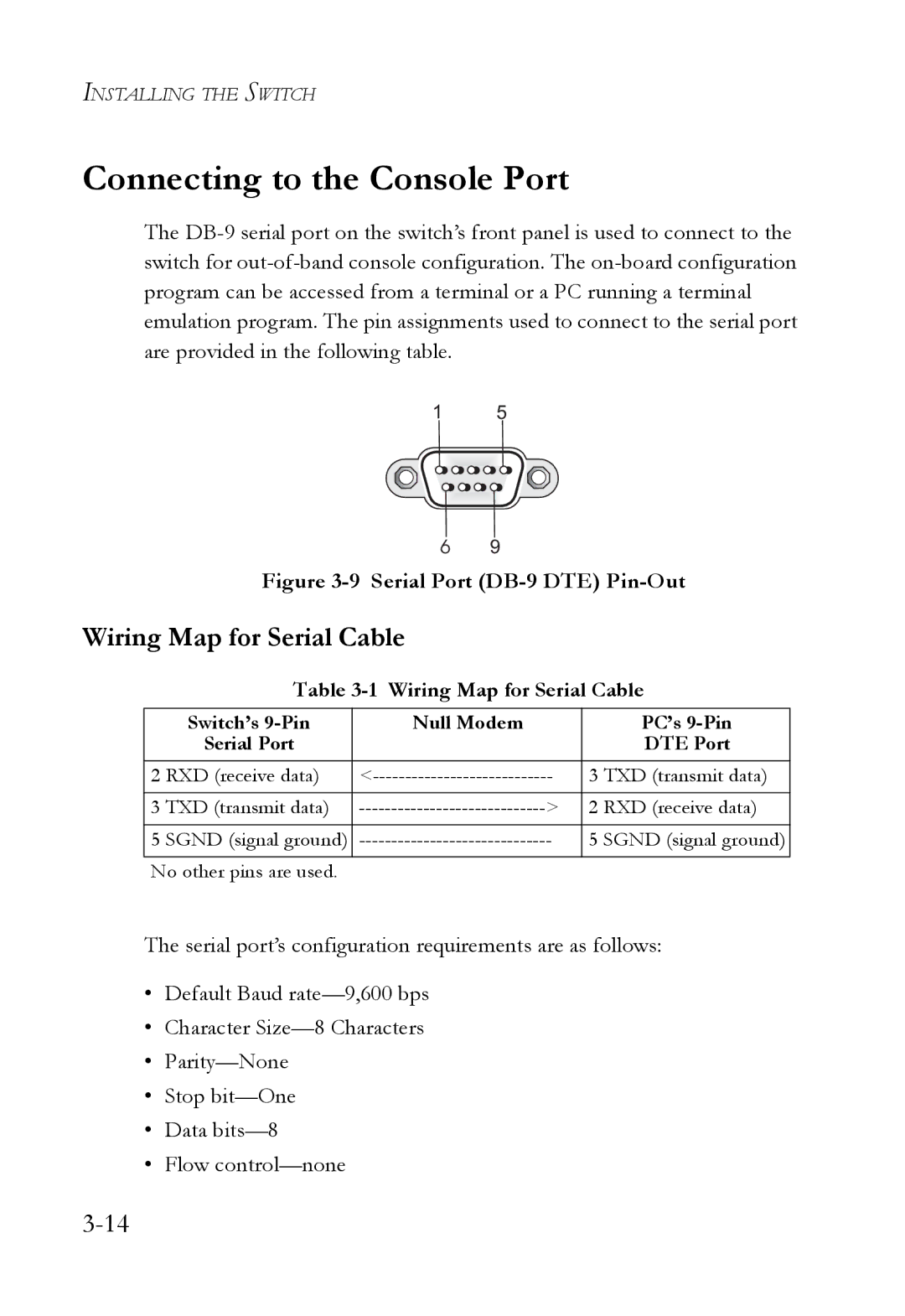
Figure 3-9 Serial Port (DB-9 DTE) Pin-Out
Wiring Map for Serial Cable
Table 3-1 Wiring Map for Serial Cable
| Switch’s | Null Modem |
|
| PC’s |
| Serial Port |
|
|
| DTE Port |
|
|
|
|
| |
2 | RXD (receive data) | 3 TXD (transmit data) | |||
|
|
|
|
|
|
3 | TXD (transmit data) | > | 2 | RXD (receive data) | |
|
|
|
|
|
|
5 | SGND (signal ground) | 5 | SGND (signal ground) | ||
|
|
|
|
|
|
No other pins are used.
The serial port’s configuration requirements are as follows:
•Default Baud
•Character
•
•Stop
•Data
•Flow