4 Panel Layout
The following figure shows the front panel layout, which is followed by a table describing in detail the status and function of each LED.
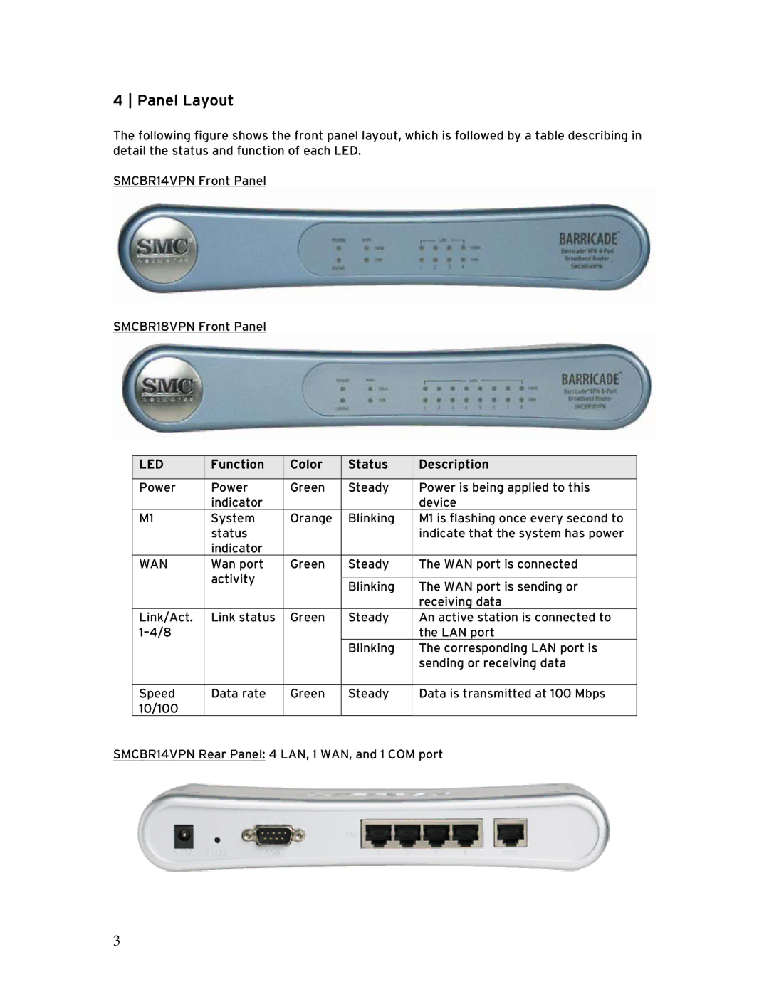
SMCBR14VPN Front Panel
SMCBR18VPN Front Panel
| LED | Function | Color | Status | Description |
|
|
|
|
|
|
| Power | Power | Green | Steady | Power is being applied to this |
|
| indicator |
|
| device |
| M1 | System | Orange | Blinking | M1 is flashing once every second to |
|
| status |
|
| indicate that the system has power |
|
| indicator |
|
|
|
| WAN | Wan port | Green | Steady | The WAN port is connected |
|
| activity |
|
|
|
|
|
| Blinking | The WAN port is sending or | |
|
|
|
| ||
|
|
|
|
| receiving data |
| Link/Act. | Link status | Green | Steady | An active station is connected to |
|
|
|
| the LAN port | |
|
|
|
| Blinking | The corresponding LAN port is |
|
|
|
|
| sending or receiving data |
|
|
|
|
|
|
| Speed | Data rate | Green | Steady | Data is transmitted at 100 Mbps |
| 10/100 |
|
|
|
|
SMCBR14VPN Rear Panel: 4 LAN, 1 WAN, and 1 COM port | |||||
3