Smeg PGF95-2, PGF95BE-2 manual Attachment to support structure, flush-mounting model

Models: PGF95-2 PGF95BE-2

1 17
Download 17 pages 30.56 Kb
Page 5
Image 5

Instructions for the installer

4)

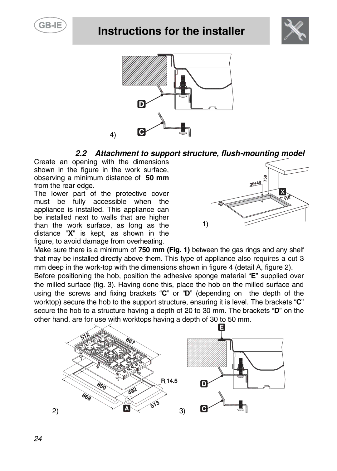
2.2Attachment to support structure, flush-mounting model

Create an opening with the dimensions

shown in the figure in the work surface,


observing a minimum distance of 50 mm


from the rear edge.


The lower part of the protective cover


must be fully accessible when the


appliance is installed. This appliance can


be installed next to walls that are higher

1)

than the work surface, as long as the

distance "X" is kept, as shown in the figure, to avoid damage from overheating.

Make sure there is a minimum of 750 mm (Fig. 1) between the gas rings and any shelf that may be installed directly above them. This type of appliance also requires a cut 3

mmdeep in the work-top with the dimensions shown in figure 4 (detail A, figure 2). Before positioning the hob, position the adhesive sponge material “E” supplied over the milled surface (fig. 3). Having done this, place the hob on the milled surface and using the screws and fixing brackets “C” or “D” (depending on the depth of the worktop) secure the hob to the support structure, ensuring it is level. The brackets “C” secure the hob to a structure having a depth of 20 to 30 mm. The brackets “D” on the other hand, are for use with worktops having a depth of 30 to 50 mm.

2)

3)

24

Page 5
Image 5
Smeg PGF95-2, PGF95BE-2 manual Attachment to support structure, flush-mounting model