| GB100W NATURAL OR PROPANE BOILER | Page 11 |
| INSTALLATION AND OPERATING INSTRUCTIONS |
|
Reverse Acting Aquastats | GAS SUPPLY PIPING |
|
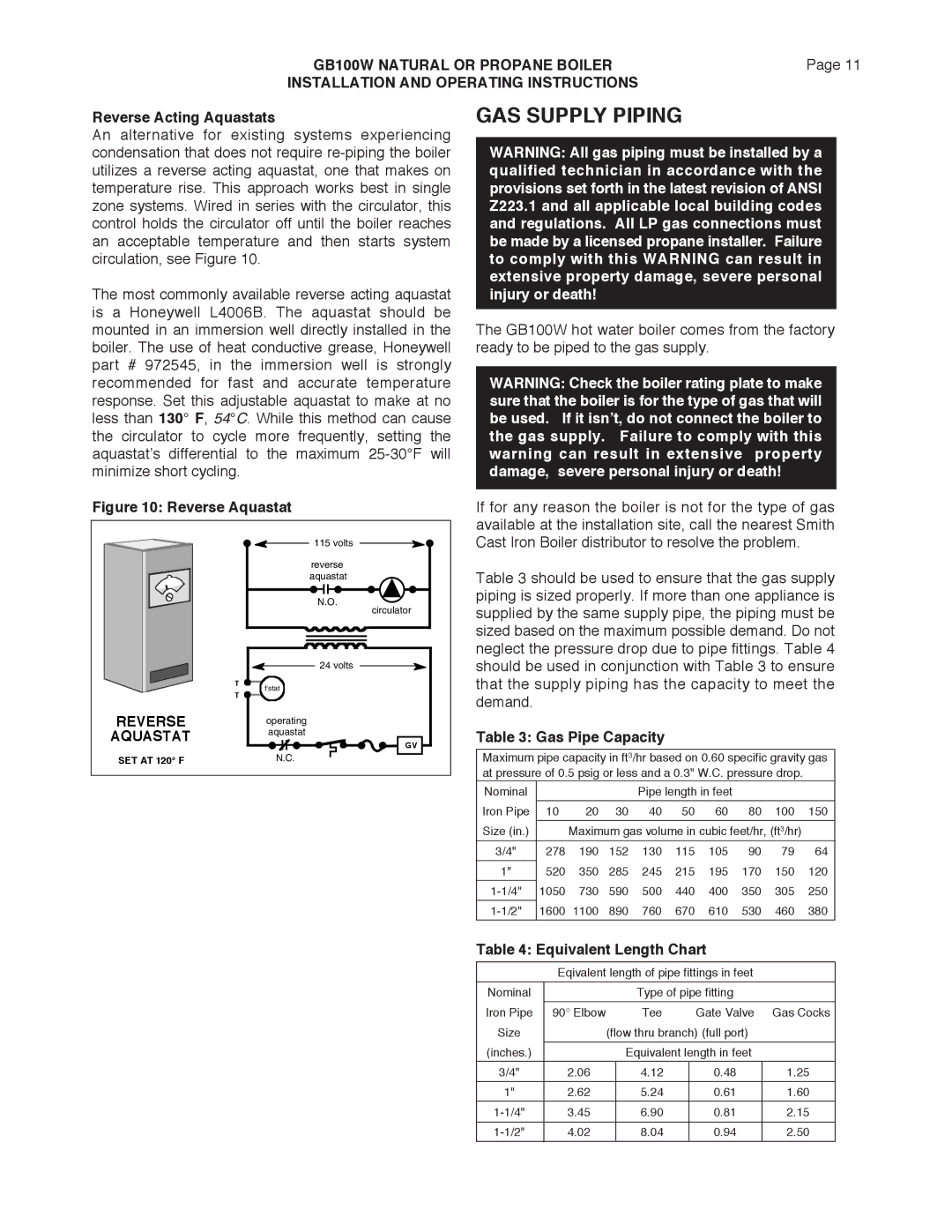
An alternative for existing systems experiencing condensation that does not require
The most commonly available reverse acting aquastat is a Honeywell L4006B. The aquastat should be mounted in an immersion well directly installed in the boiler. The use of heat conductive grease, Honeywell part # 972545, in the immersion well is strongly recommended for fast and accurate temperature response. Set this adjustable aquastat to make at no less than 130° F, 54°C. While this method can cause the circulator to cycle more frequently, setting the aquastat’s differential to the maximum
Figure 10: Reverse Aquastat
| 115 volts | |
| reverse | |
| aquastat | |
| N.O. | |
| circulator | |
| 24 volts | |
| T | |
| t'stat | |
| T | |
REVERSE | operating | |
AQUASTAT | aquastat | |
GV | ||
| ||
SET AT 120° F | N.C. |
WARNING: All gas piping must be installed by a qualified technician in accordance with the provisions set forth in the latest revision of ANSI Z223.1 and all applicable local building codes and regulations. All LP gas connections must be made by a licensed propane installer. Failure to comply with this WARNING can result in extensive property damage, severe personal injury or death!
The GB100W hot water boiler comes from the factory ready to be piped to the gas supply.
WARNING: Check the boiler rating plate to make sure that the boiler is for the type of gas that will be used. If it isn’t, do not connect the boiler to the gas supply. Failure to comply with this warning can result in extensive property damage, severe personal injury or death!
If for any reason the boiler is not for the type of gas available at the installation site, call the nearest Smith Cast Iron Boiler distributor to resolve the problem.
Table 3 should be used to ensure that the gas supply piping is sized properly. If more than one appliance is supplied by the same supply pipe, the piping must be sized based on the maximum possible demand. Do not neglect the pressure drop due to pipe fittings. Table 4 should be used in conjunction with Table 3 to ensure that the supply piping has the capacity to meet the demand.
Table 3: Gas Pipe Capacity
Maximum pipe capacity in ft3/hr based on 0.60 specific gravity gas at pressure of 0.5 psig or less and a 0.3" W.C. pressure drop.
Nominal |
|
|
| Pipe length in feet |
|
|
| ||
|
|
|
|
|
|
|
|
|
|
Iron Pipe | 10 | 20 | 30 | 40 | 50 | 60 | 80 | 100 | 150 |
|
|
|
| ||||||
Size (in.) |
| Maximum gas volume in cubic feet/hr, (ft3/hr) |
| ||||||
3/4" | 278 | 190 | 152 | 130 | 115 | 105 | 90 | 79 | 64 |
|
|
|
|
|
|
|
|
|
|
1" | 520 | 350 | 285 | 245 | 215 | 195 | 170 | 150 | 120 |
1050 | 730 | 590 | 500 | 440 | 400 | 350 | 305 | 250 | |
1600 | 1100 | 890 | 760 | 670 | 610 | 530 | 460 | 380 | |
Table 4: Equivalent Length Chart
Eqivalent length of pipe fittings in feet
Nominal |
|
| Type of pipe fitting |
| |
|
|
|
|
|
|
Iron Pipe | 90° Elbow |
| Tee | Gate Valve | Gas Cocks |
Size |
| (flow thru branch) (full port) |
| ||
|
|
|
|
|
|
(inches.) |
|
| Equivalent length in feet |
| |
3/4" | 2.06 |
| 4.12 | 0.48 | 1.25 |
|
|
|
|
|
|
1" | 2.62 |
| 5.24 | 0.61 | 1.60 |
3.45 |
| 6.90 | 0.81 | 2.15 | |
|
|
|
|
|
|
4.02 |
| 8.04 | 0.94 | 2.50 | |
|
|
|
|
|
|
