Page 6

GT INSTALLATION AND OPERATION INSTRUCTIONS

The vent terminal shall not terminate:

Directly above a paved sidewalk or a paved drive-way that is located between two buildings, and that serves both buildings;

Less than 7 ft, 2.1 m above grade where located adjacent to a paved driveway or public walkway.

Within 3 ft, 0.9 m, horizontally of a window or door that can be opened, or non-mechanical air supply inlet to any building.

Within 6 ft, 1.8 m, of a mechanical air supply inlet to any building or roof eve containing soffit openings.

Above a meter/regulator assembly within 3 ft, 0.9 m, horizontally of the vertical centerline of the regulator.

Within 6 ft, 1.8 m, of any gas service regulator vent outlet.

Less than 30 in, 762 mm, plus snow allowance above grade, or any surface that will support snow, ice, or debris. The exhaust must be a minimum of 18 in, 457 mm, above the air inlet, and the air inlet must always be a minimum of 12 in, 305 mm. plus snow allowance above any surface that will support snow. A 24 in, 610 mm, plus snow allowance is highly recommended. Consult your weather office, for the maximum typical snowfall for your region.

Underneath a verandah, porch, or deck.

So situated that the fl ue gases are directed towards brickwork, siding, or other construction, in such a manner that may cause damage from heat or condensate from the flue gases.

Less than 3 ft, 0.9 m, from an inside corner of an L-shaped structure including walls and fences. Under normal operating conditions this appliance will produce a plume of water vapor, and should be taken into consideration when selecting an adequate vent terminal location. A 3 ft, 0.9 m, diameter stainless, plastic, or vinyl shield can be used to flash the exterior of the residence to protect is from damage.

Separate Air Intake and Vent Terminals

It is highly recommended that the air intake and vent terminals not be located where they will be exposed to normal prevailing winds. Both terminals must be on the same wall.

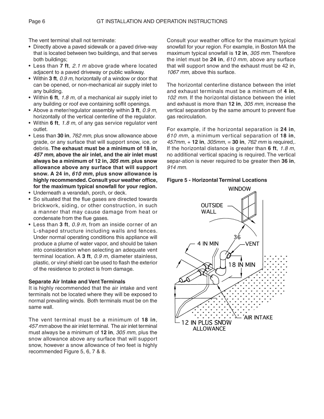
The vent terminal must be a minimum of 18 in, 457 mm above the air inlet terminal. The air inlet terminal must always be a minimum of 12 in, 305 mm, plus the snow allowance above any surface that will support snow, however a snow allowance of two feet is highly recommended Figure 5, 6, 7 & 8.

Consult your weather office for the maximum typical snowfall for your region. For example, in Boston MA the maximum typical snowfall is 12 in, 305 mm. Therefore the inlet must be 24 in, 610 mm, above any surface that will support snow and the exhaust must be 42 in, 1067 mm, above this surface.

The horizontal centerline distance between the inlet and exhaust terminals must be a minimum of 4 in, 102 mm. If the horizontal distance between the inlet and exhaust is more than 12 in, 305 mm, increase the vertical separation by the same amount to prevent fl ue gas recirculation.

For example, if the horizontal separation is 24 in, 610 mm, a minimum vertical separation of 18 in, 457mm, + 12 in, 305mm, = 30 in, 762 mm is required,. If the horizontal distance is greater than 6 ft, 1.8 m, no additional vertical spacing is required. The vertical separ-ation is never required to be greater then 36 in, 914 mm.

Figure 5 - Horizontal Terminal Locations

Page 6
Image 6
Smith Cast Iron Boilers GT Series manual Separate Air Intake and Vent Terminals, Horizontal Terminal Locations

GT Series specifications

Smith Cast Iron Boilers GT Series has become a benchmark in the hydronic heating industry, renowned for its exceptional performance, durability, and efficiency. This series is designed to cater to diverse heating needs, making it a popular choice among both residential and commercial applications.

One of the standout features of the GT Series is its robust cast iron construction. The cast iron sections offer superior thermal mass, allowing for better heat retention and distribution. This characteristic ensures that the boiler operates efficiently, maintaining comfortable temperatures even during extreme cold weather conditions. The engineers at Smith have meticulously designed each section to provide maximum strength and longevity, resulting in a boiler that can withstand the test of time.

The GT Series also incorporates advanced combustion technology. It utilizes a high-efficiency burner that optimizes fuel consumption, resulting in lower operating costs for homeowners and businesses alike. The boiler is engineered to accommodate a variety of fuel types, including natural gas and propane, giving users flexibility in their energy choices. This adaptability not only enhances efficiency but also promotes environmental sustainability by allowing for the use of cleaner fuel sources.

Another notable technology featured in the GT Series is the electronic control system. This system simplifies boiler operation and enhances user convenience. The intuitive interface provides real-time feedback and diagnostics, making it easier for technicians to perform maintenance and troubleshoot any issues that may arise. Additionally, the boiler’s modulating operation adjusts the burner output according to the heating demand, further improving efficiency and comfort.

Moreover, the GT Series is designed with user-friendly installation in mind. Its compact footprint allows for easy integration into existing heating systems, minimizing space requirements. Additionally, the boiler is equipped with convenient access points for maintenance, ensuring that servicing is straightforward and can be performed without extensive downtime.

Lastly, the Smith Cast Iron Boilers GT Series is designed to meet stringent safety and performance standards. Featuring multiple safety controls and systems, it provides peace of mind for users. With a commitment to quality, efficiency, and performance, the GT Series stands out as a leading solution for hydronic heating, catering to the evolving needs of today’s energy-conscious consumers.