GT Series specifications
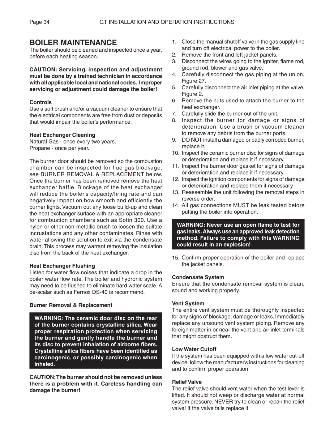
Smith Cast Iron Boilers GT Series has become a benchmark in the hydronic heating industry, renowned for its exceptional performance, durability, and efficiency. This series is designed to cater to diverse heating needs, making it a popular choice among both residential and commercial applications.One of the standout features of the GT Series is its robust cast iron construction. The cast iron sections offer superior thermal mass, allowing for better heat retention and distribution. This characteristic ensures that the boiler operates efficiently, maintaining comfortable temperatures even during extreme cold weather conditions. The engineers at Smith have meticulously designed each section to provide maximum strength and longevity, resulting in a boiler that can withstand the test of time.
The GT Series also incorporates advanced combustion technology. It utilizes a high-efficiency burner that optimizes fuel consumption, resulting in lower operating costs for homeowners and businesses alike. The boiler is engineered to accommodate a variety of fuel types, including natural gas and propane, giving users flexibility in their energy choices. This adaptability not only enhances efficiency but also promotes environmental sustainability by allowing for the use of cleaner fuel sources.
Another notable technology featured in the GT Series is the electronic control system. This system simplifies boiler operation and enhances user convenience. The intuitive interface provides real-time feedback and diagnostics, making it easier for technicians to perform maintenance and troubleshoot any issues that may arise. Additionally, the boiler’s modulating operation adjusts the burner output according to the heating demand, further improving efficiency and comfort.
Moreover, the GT Series is designed with user-friendly installation in mind. Its compact footprint allows for easy integration into existing heating systems, minimizing space requirements. Additionally, the boiler is equipped with convenient access points for maintenance, ensuring that servicing is straightforward and can be performed without extensive downtime.
Lastly, the Smith Cast Iron Boilers GT Series is designed to meet stringent safety and performance standards. Featuring multiple safety controls and systems, it provides peace of mind for users. With a commitment to quality, efficiency, and performance, the GT Series stands out as a leading solution for hydronic heating, catering to the evolving needs of today’s energy-conscious consumers.

