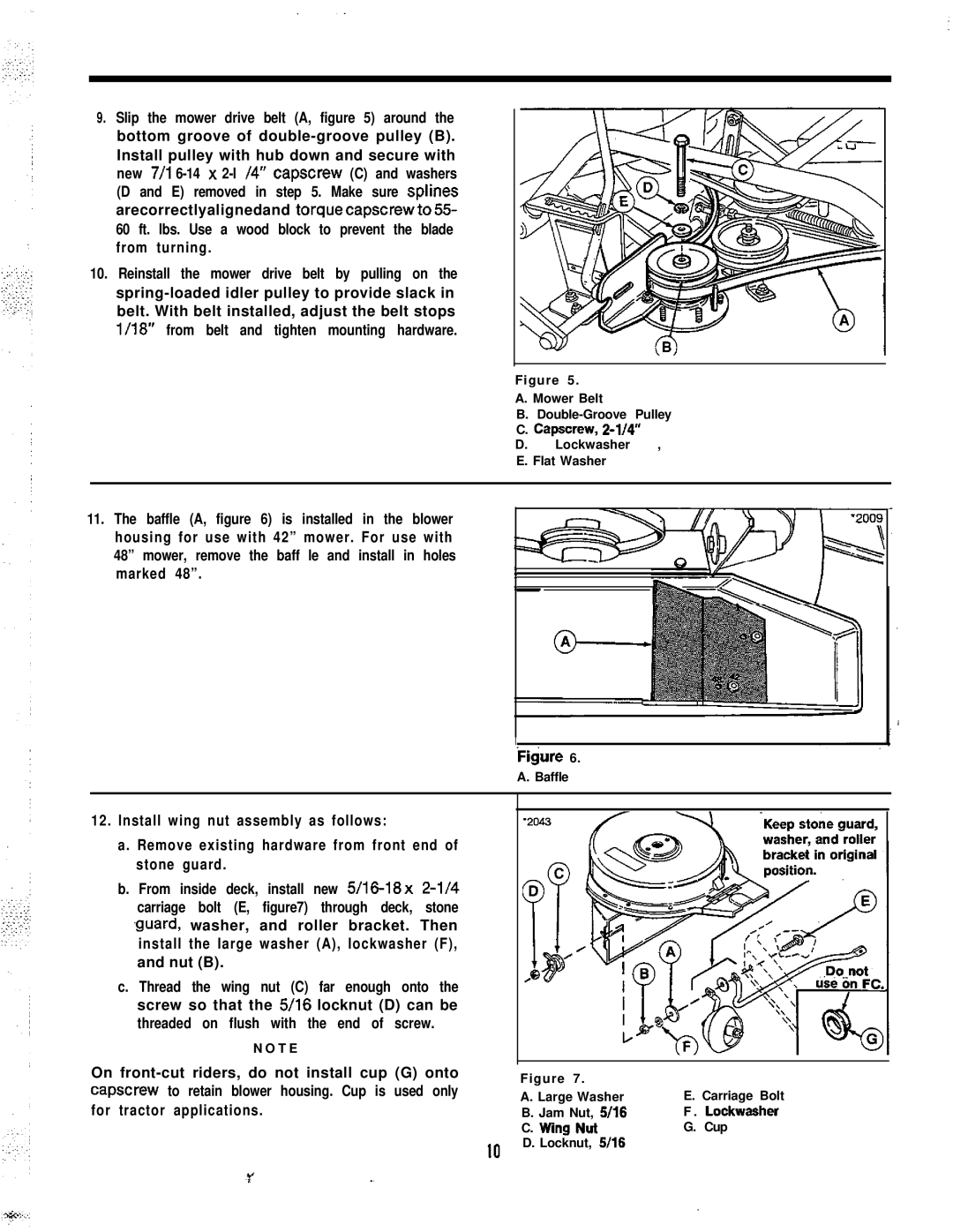
9.Slip the mower drive belt (A, figure 5) around the bottom groove of
10.Reinstall the mower drive belt by pulling on the
Figure 5.
A. Mower Belt
B.
C. Capscrew,
D. Lockwasher ,
E. Flat Washer
11.The baffle (A, figure 6) is installed in the blower housing for use with 42” mower. For use with 48” mower, remove the baff le and install in holes marked 48”.
I
-
Figure 6.
A. Baffle
12.Install wing nut assembly as follows:
a.Remove existing hardware from front end of stone guard.
b.From inside deck, install new
.guard, washer, and roller bracket. Then install the large washer (A), lockwasher (F), and nut (B).
c.Thread the wing nut (C) far enough onto the screw so that the 5/16 locknut (D) can be threaded on flush with the end of screw.
N O T E
On
Figure 7. |
|
|
A. Large Washer | E. Carriage Bolt | |
B. Jam Nut, | 5/16 | F . Lockwasher |
C. Wing Nut |
| G. Cup |
D. Locknut, | 5116 |
|
IO
