Initial Counter Balance & Weight
Carrier Installation
| B |
|
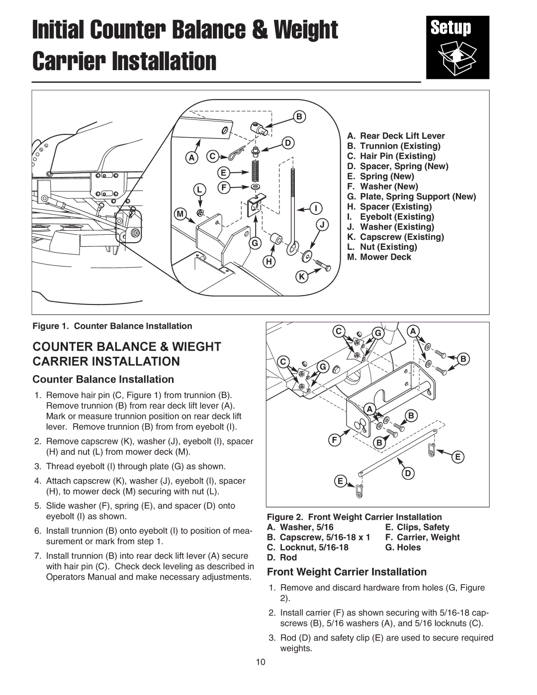
| D | A. Rear Deck Lift Lever |
| B. Trunnion (Existing) | |
|
| |
A | C | C. Hair Pin (Existing) |
| E | D. Spacer, Spring (New) |
| E. Spring (New) | |
|
| |
L | F | F. Washer (New) |
|
| G. Plate, Spring Support (New) |
M | I | H. Spacer (Existing) |
J | I. Eyebolt (Existing) | |
| J. Washer (Existing) | |
| G | K. Capscrew (Existing) |
| L. Nut (Existing) | |
|
| |
| H | M. Mower Deck |
|
|
| K |
|
|
| |
Figure 1. Counter Balance Installation |
| C | G | A | |
|
| ||||
COUNTER BALANCE & WIEGHT | C | G |
|
| |
CARRIER INSTALLATION |
| B | |||
|
|
|
| ||
Counter Balance Installation |
|
|
|
| |
1. Remove hair pin (C, Figure 1) from trunnion (B). |
|
|
|
| |
Remove trunnion (B) from rear deck lift lever (A). |
| A |
| B | |
Mark or measure trunnion position on rear deck lift |
|
| |||
|
|
| |||
lever. Remove trunnion (B) from from eyebolt (I). |
|
|
|
| |
2. Remove capscrew (K), washer (J), eyebolt (I), spacer |
| F | B |
| |
(H) and nut (L) from mower deck (M). |
|
|
| E | |
3. Thread eyebolt (I) through plate (G) as shown. |
|
|
| ||
|
|
| D | ||
4. Attach capscrew (K), washer (J), eyebolt (I), spacer |
| E |
| ||
|
|
| |||
(H), to mower deck (M) securing with nut (L). |
|
|
|
| |
5. Slide washer (F), spring (E), and spacer (D) onto |
|
|
|
| |
eyebolt (I) as shown. | Figure 2. | Front Weight Carrier Installation | |||
6. Install trunnion (B) onto eyebolt (I) to position of mea- | A. Washer, 5/16 |
| E. Clips, Safety | ||
B. Capscrew, |
| F. Carrier, Weight | |||
surement or mark from step 1. |
| ||||
C. Locknut, |
| G. Holes | |||
7. Install trunnion (B) into rear deck lift lever (A) secure |
| ||||
D. Rod |
|
|
| ||
with hair pin (C). Check deck leveling as described in | Front Weight Carrier Installation | ||||
Operators Manual and make necessary adjustments. | |||||
|
|
|
| ||
| 1. Remove and discard hardware from holes (G, Figure | ||||
| 2). |
|
|
| |
| 2. Install carrier (F) as shown securing with | ||||
| screws (B), 5/16 washers (A), and 5/16 locknuts (C). | ||||
| 3. Rod (D) and safety clip (E) are used to secure required | ||||
| weights. |
|
| ||
| 10 |
|
|
| |